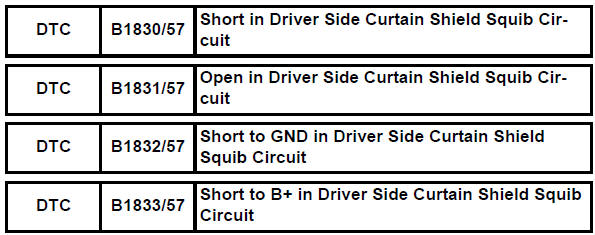
Toyota RAV4 (XA40) 2013-2018 Service Manual: Short in driver side curtain shield squib circuit
Description
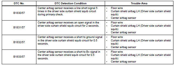
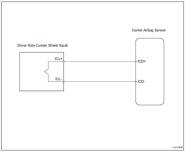
The driver side curtain shield squib circuit consists of the center airbag sensor and the curtain shield airbag lh.
The circuit instructs the srs to deploy when the deployment conditions are met.
These dtcs are recorded when a malfunction is detected in the driver side curtain shield squib circuit.
Wiring diagram
Inspection procedure
Hint:
- Perform the simulation method by selecting the "check mode" (signal check) with the intelligent tester (see page rs-49).
- After selecting the "check mode" (signal check), perform the simulation method by wiggling each connector of the airbag system or driving the vehicle on a city or rough road (see page rs-49).
- Check curtain shield airbag assembly lh (driver side curtain shield squib)
- Turn the ignition switch off.
- Disconnect the cable from the negative (-) battery terminal, and wait for at least 90 seconds.
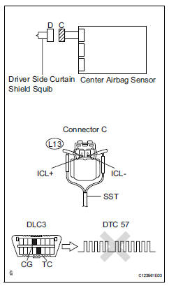
- Disconnect the connector from the curtain shield airbag lh.
- Connect the white wire side of sst (resistance 2.1 Ù) to connector c.
Caution:
Never connect a tester to the curtain shield airbag lh (driver side curtain shield squib) for measurement, as this may lead to a serious injury due to airbag deployment.
Notice:
- Do not forcibly insert sst into the terminals of the connector when connecting.
- Insert sst straight into the terminals of the connector.
Sst 09843-18060
- Connect the cable to the negative (-) battery terminal, and wait for at least 2 seconds.
- Turn the ignition switch on, and wait for at least 60 seconds.
- Clear the dtcs (see page rs-49).
- Turn the ignition switch off.
- Turn the ignition switch on, and wait for at least 60 seconds.
- Check the dtcs (see page rs-49).
Ok: dtc b1830, b1831, b1832, b1833 or 57 is not output.
Hint:
Dtcs other than dtc b1830, b1831, b1832, b1833 or 57 may be output at this time, but they are not related to this check.

- Check connector
- Turn the ignition switch off.
- Disconnect the cable from the negative (-) battery terminal, and wait for at least 90 seconds.
- Disconnect sst from connector c.
- Check that the floor wire connector (on the curtain shield lh side) is not damaged.
Ok: lock button is not disengaged, and claw of lock is not deformed or damaged.


- Check floor wire (driver side curtain shield squib circuit)
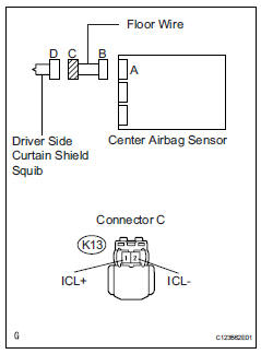
- Disconnect the connector from the center airbag sensor.
- Connect the cable to the negative (-) battery terminal, and wait for at least 2 seconds.
- Turn the ignition switch on.
- measure the voltage of the wire harness side connector.
Standard voltage 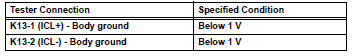
- Turn the ignition switch off.
- Disconnect the cable from the negative (-) battery terminal, and wait for at least 90 seconds.
- Measure the resistance of the wire harness side connector
Standard resistance 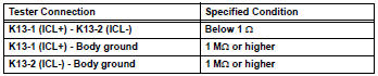
- Release the activation prevention mechanism built into connector b (see page rs-37).
- Measure the resistance of the wire harness side connector.
Standard resistance 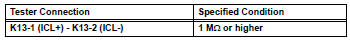

Replace center airbag sensor assembly
 Short in front passenger side - side squib circuit
Description
The front passenger side - side squib circuit consists of the center airbag
sensor and the front seat side
airbag rh.
The circuit instructs the srs to deploy when the deployment ...
 Short in front passenger side curtain shield squib circuit
Description
The front passenger side curtain shield squib circuit consists of the center
airbag sensor and the curtain
shield airbag rh.
The circuit instructs the srs to deploy when the dep ...
Other materials:
Back-up power source circuit
Description
This is the back-up power source circuit for the air conditioning amplifier.
Power is supplied even when the
ignition switch is turned off and is used for functions such as the diagnostic
trouble code memory.
wiring diagram
Inspection procedure
Inspect fuse (ecu-b2)
...
Removal
Disconnect cable from negative battery
terminal
Caution:
Wait at least 90 seconds after disconnecting the
cable from the negative (-) battery terminal to
prevent airbag and seat belt pretensioner activation.
Remove front fender liner lh
Remove front fender liner lh
Remove the ...
Components
Fuse boxes
Engine oil filler cap
Engine oil level dipstick
Battery
Brake fluid reservoir
Radiator
Electric cooling fan
Condenser
Washer fluid tank
Engine coolant reservoir
Checking the engine oil
With the engine at operating
temperature and turned off,
check the oil level on the di ...
