Toyota RAV4 (XA40) 2013-2018 Service Manual: Short in front passenger side curtain shield squib circuit
Description
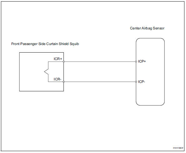
The front passenger side curtain shield squib circuit consists of the center airbag sensor and the curtain shield airbag rh.
The circuit instructs the srs to deploy when the deployment conditions are met.
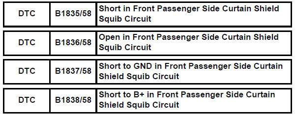
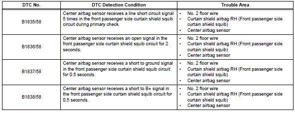
These dtcs are recorded when a malfunction is detected in the front passenger side curtain shield squib circuit.
Wiring diagram
Inspection procedure
Hint:
- Perform the simulation method by selecting the "check mode" (signal check) with the intelligent tester (see page rs-52).
- After selecting the "check mode" (signal check), perform the simulation method by wiggling each connector of the airbag system or driving the vehicle on a city or rough road (see page rs-52).
- Check curtain shield airbag assembly rh (front passenger side curtain shield squib)
- Turn the ignition switch off.
- Disconnect the cable from the negative (-) battery terminal, and wait for at least 90 seconds.
- Disconnect the connectors from the curtain shield airbag rh.
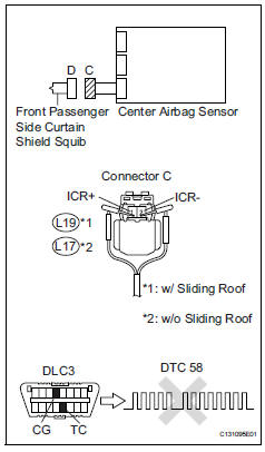
- Connect the white wire side of sst to connector c.
Caution:
Never connect a tester to the curtain shield airbag rh (front passenger side curtain shield squib) for measurement, as this may lead to a serious injury due to airbag deployment.
Notice:
- Do not forcibly insert sst into the terminals of the connector when connecting.
- Insert sst straight into the terminals of the connector.
Sst 09843-18060
- Connect the cable to the negative (-) battery terminal, and wait for at least 2 seconds
- Turn the ignition switch on, and wait for at least 60 seconds.
- Clear the dtcs (see page rs-49).
- Turn the ignition switch off.
- Turn the ignition switch on, and wait for at least 60 seconds.
- Check the dtcs (see page rs-49).
Ok: dtc b1835, b1836, b1837, b1838 or 58 is not output.
Hint:
Dtcs other than dtc b1835, b1836, b1837, b1838 or 58 may be output at this time, but they are not related to this check.

- Check connector
- Turn the ignition switch off.
- Disconnect the cable from the negative (-) battery terminal, and wait for at least 90 seconds.
- Disconnect sst from connector c.
- Check that the floor wire connector (on the curtain shield airbag rh side) is not damaged.
Ok: lock button is not disengaged, and claw of lock is not deformed or damaged.


- Check floor wire no.2 (Front passenger side curtain shield squib circuit)
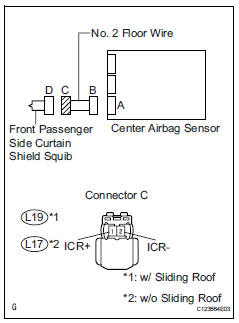
- Disconnect the connectors from the center airbag sensor.
- Connect the cable to the negative (-) battery terminal, and wait for at least 2 seconds.
- Turn the ignition switch on.
- Measure the voltage of the wire harness side connector.
Standard voltage:
W/ sliding roof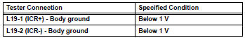
W/o sliding roof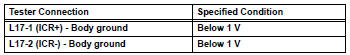
- Turn the ignition switch off.
- Disconnect the cable from the negative (-) battery terminal, and wait for at least 90 seconds.
- Measure the resistance of the wire harness side connector.
Standard resistance:
W/ sliding roof 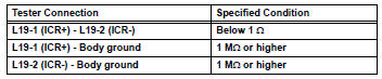
W/o sliding roof 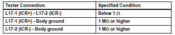
- Release the activation prevention mechanism built into connector b (see page rs-37).
- Measure the resistance of the wire harness side connector.
Standard resistance:
W/ sliding roof 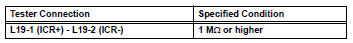
W/o sliding roof 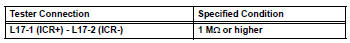

Replace center airbag sensor assembly
 Short in driver side curtain shield squib circuit
Description
The driver side curtain shield squib circuit consists of the center airbag
sensor and the curtain shield
airbag lh.
The circuit instructs the srs to deploy when the deployment c ...
 Short in front driver side pretensioner squib circuit
Description
The driver side front pretensioner squib circuit consists of the center
airbag sensor and the front seat
outer belt lh.
This circuit instructs the srs to deploy when the deploym ...
Other materials:
Replacement
Replace generator drive end frame bearing
Remove the 4 screws and bearing retainer.
Using sst and a hammer, tap out the bearing.
Sst 09950-60010 (09951-00250), 09950-70010
(09951-07100)
Using sst and a press, press in a new bearing.
Sst 09950-60010 (09951-00250), 09 ...
Throttle actuator control throttle body range / performance
Description
The electronic throttle control system (etcs) is composed of the throttle
actuator, throttle position (tp)
sensor, accelerator pedal position (app) sensor, and ecm. The ecm operates the
throttle actuator to
regulate the throttle valve in response to driver inputs. The tp senso ...
Front passenger side rear airbag sensor circuit malfunction
Description
The rear airbag sensor rh consists of parts including the diagnostic circuit
and the lateral deceleration
sensor.
When the center airbag sensor receives signals from the lateral deceleration
sensor, it determines
whether or not the srs should be activated.
Dtc b1635/24 i ...
