Toyota RAV4 (XA40) 2013-2018 Service Manual: Terminals of ecu (2006/01- )
- Check air conditioning amplifier
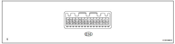
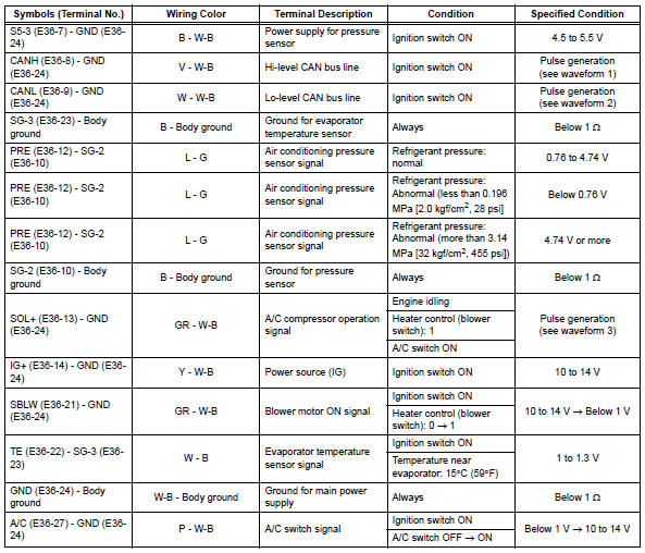
- Measure the voltage and resistance of the connectors.
Hint:
Check from the rear of the connector while it is connected to the air conditioning amplifier.
Hint:
*: For 2gr-fe
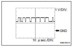
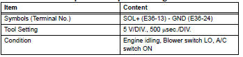
- Using an oscilloscope, check waveform 1.
Can communication signal 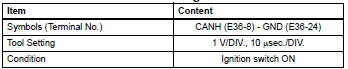
Hint:
The waveform varies depending on the can communication signal.
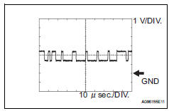
- Using an oscilloscope, check waveform 2.
Can communication signal 
Hint:
The waveform varies depending on the can communication signal.
- Using an oscilloscope, check waveform 3.
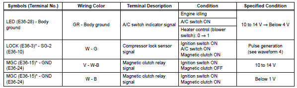
A/c compressor* operation signal
Hint:
*: Compressor and pulley for 2az-fe, compressor and magnetic clutch for 2gr-fe
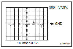
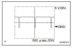
- Using an oscilloscope, check waveform 4.
Compressor lock sensor signal* 
Hint:
*: For 2gr-fe
 Terminals of ecu (2005/11-2006/01)
Check air conditioning amplifier
Measure the voltage and resistance of the
connectors.
Hint:
Check from the rear of the connector while it is
connected to the air conditioning ampl ...
 Diagnosis system
Description
Air conditioning system data and the diagnostic
trouble codes (dtcs) can be read through the
data link connector 3 (dlc3) of the vehicle. When
the system seems to be malfunc ...
Other materials:
Problem symptoms table (2005/11-2006/01)
Hint:
Use the table below to help determine the cause of the
problem symptom. The potential causes of the symptoms
are listed in order of probability in the "suspected area"
column of the table. Check each symptom by checking the
suspected areas in the order they are listed. Re ...
Child restraint system
fixed with a child restraint
LATCH anchor
â– Child restraint LATCH
anchors
LATCH anchors are provided for
the outboard rear seats.
â– When installing in the rear
outboard seats
Install the child restraint system
in accordance to the operation
manual enclosed with the child
restraint system.
1. Adjust the seat.
If there is a gap between ...
Basic audio operations
Basic audio operations and functions common to each mode are
explained in this section.
Operating the audio system
Press this knob to turn the
audio system on and off, and
turn it to adjust the volume.
Press this button to eject a disc
Insert a disc into the disc slot
Press to pa ...
