
Toyota RAV4 (XA40) 2013-2018 Service Manual: Terminals of ecu (2005/11-2006/01)
- Check air conditioning amplifier
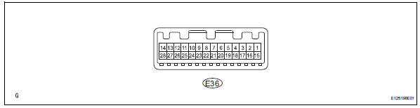
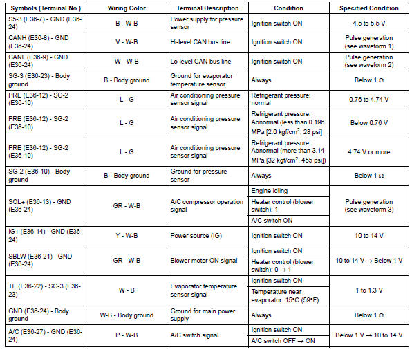
- Measure the voltage and resistance of the connectors.
Hint:
Check from the rear of the connector while it is connected to the air conditioning amplifier.

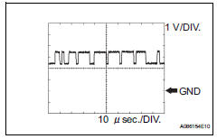
- using an oscilloscope, check waveform 1.
Can communication signal 
Hint:
The waveform varies depending on the can communication signal.
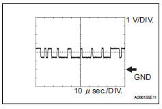
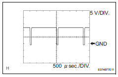
- Using an oscilloscope, check waveform 2.
Can communication signal 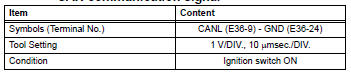
Hint:
The waveform varies depending on the can communication signal.
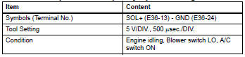
- Using an oscilloscope, check waveform 3.
Compressor and pulley operation signal
 Problem symptoms table (2006/01- )
Hint:
Use the table below to help determine the cause of the
problem symptom. The potential causes of the symptoms
are listed in order of probability in the "suspected area"
colum ...
 Terminals of ecu (2006/01- )
Check air conditioning amplifier
Measure the voltage and resistance of the
connectors.
Hint:
Check from the rear of the connector while it is
connected to the air conditioning ampl ...
Other materials:
Air outlet damper control servo motor circuit
Description
The damper servo sends pulse signals to indicate the damper position to the
air conditioning amplifier.
The air conditioning amplifier activates the motor (normal or reverse) based on
these signals to move the
mode damper to the appropriate position, which controls the air o ...
Srs warning light remains on
Description
The srs warning light is located on the combination meter.
When the srs is normal, the srs warning light comes on for approximately 6
seconds after the ignition
switch is turned from off to on, and then goes off automatically.
If there is a malfunction in the srs, the srs warni ...
Evaporative emission system switching valve control
Dtc summary
Hint:
The vent valve is built into the canister pump module.
Description
The description can be found in the evap (evaporative emission) system (see
page es-335).
Inspection procedure
Refer to the evap system (see page es-340).
Monitor description
5 Hours* after the ign ...
