Toyota RAV4 (XA40) 2013-2018 Service Manual: System diagram
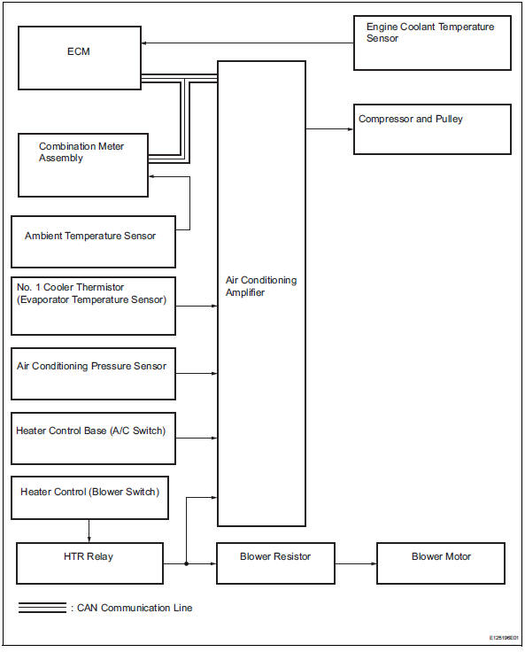
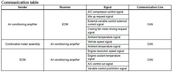
System diagram (2005/11-2006/01)
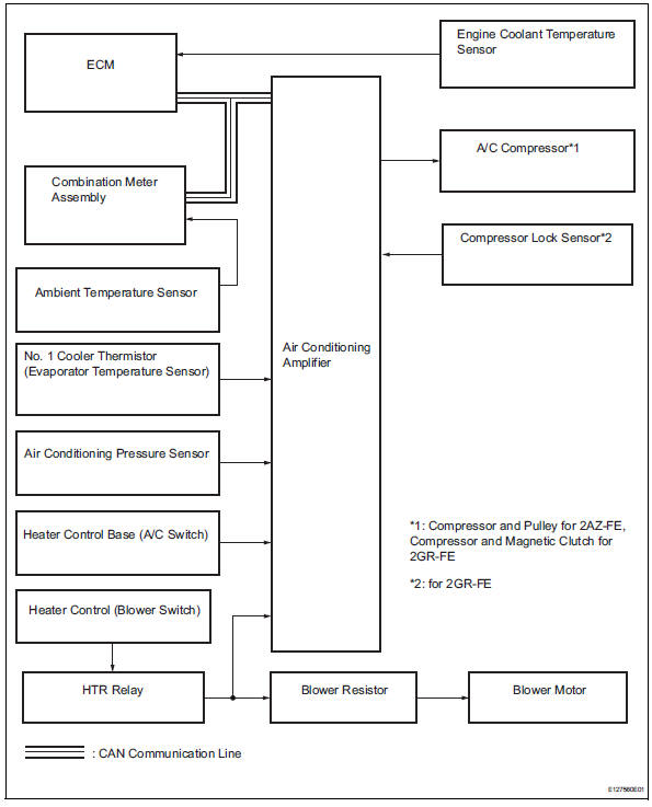
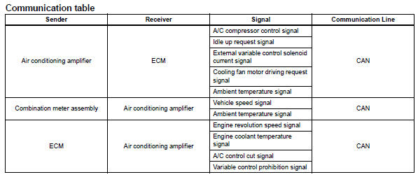
System diagram (2006/01- )

 System description
General
The air conditioning system has the following
features:
The air conditioning amplifier controls the
operation of parts, such as the a/c compressor,
automatically in accord ...
Other materials:
Camshaft position sensor "a" circuit (bank 1 or single sensor)
Description
The camshaft position (cmp) sensor consists of a magnet and an iron core
which is wrapped with copper
wire, and is installed onto the cylinder head. When the camshaft rotates, each
of 3 teeth on the camshaft
passes through the cmp sensor. This activates the internal magnet in ...
Disassembly
Hint:
When removing the ornament plate and emblem, heat the
radiator grille, ornament plate and emblem using a heat light.
Standard heating temperature
Notice:
Do not heat the emblem base and emblem excessively.
Remove hood to radiator grille seal
Remove the double-side tape.
Deta ...
Battery current sensor
On-vehicle inspection
Check battery current sensor assembly
Measure the resistance of the sensor.
Standard resistance
If the result is not as specified, replace the sensor
assembly.
Measure the resistance of the sensor.
Standard resistance
If the result is not as specified, ...
