Toyota RAV4 (XA40) 2013-2018 Service Manual: Cruise control system cruise control main switch
Components
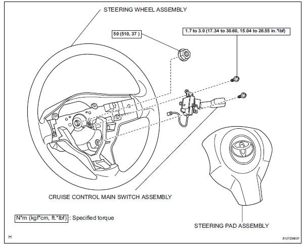
Removal
Caution:
Be sure to read the precautionary notices concerning the srs airbag system before servicing it (see page rs-1).
- Disconnect cable from negative battery terminal
Caution:
Wait at least 90 seconds after disconnecting the cable from the negative (-) battery terminal to prevent airbag and seat belt pretensioner activation.
- Remove steering pad assembly (see page rs- 336)
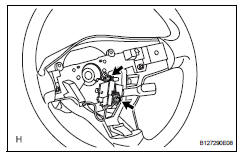
- Remove cruise control main switch
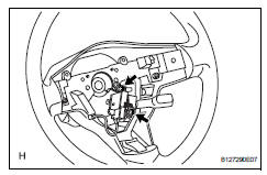
- Disconnect the connector.
- Remove the 2 screws and switch.
Inspection
- Inspect cruise control main switch
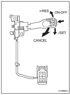
- Measure the resistance of the switch.
Standard resistance 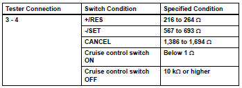
If the result is not as specified, replace the switch assembly.
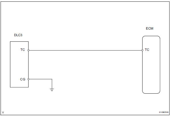
Tc and cg terminal circuit
Description
Connecting terminals tc and cg of the dlc3 enables dtcs to be read through blinking patterns of the combination meter's cruise main indicator light.
Hint:
When a warning light of the combination meter blinks continuously, terminal tc of the dlc3 or an ecm may have a ground short.
Wiring diagram
Inspection procedure
- Check wire harness (dlc3 - ecm and body ground)
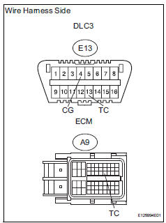
- Disconnect the e13 dlc3 connector.
- Disconnect the a9 ecm connector.
- Measure the resistance of the wire harness side connectors.
Standard resistance 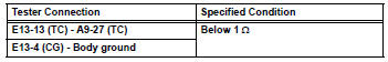

Replace ecm
Installation
- Install cruise control main switch
- Install the switch with the 2 screws.
Torque: 1.7 To 3.0 N*m (17.34 To 30.60 Kgf*cm, 15.04 To 26.55 In.*Lbf)
- Connect the connector.
- Install steering pad assembly (see page rs- 336)
- Connect cable to negative battery terminal
- Check srs warning light
- Check the srs warning light (see page rs-37).
 Cruise control switch circuit
Description
This circuit sends signals to the ecm depending on the cruise control switch
condition. The battery
supplies positive (+) battery voltage to the cruise control switch. Then
terminal ...
 Differential
...
Other materials:
Back door outside garnish
Components
Removal
Disconnect cable from negative battery
terminal
Caution:
Wait at least 90 seconds after disconnecting the
cable from the negative (-) battery terminal to
prevent airbag and seat belt pretensioner activation.
Remove back door center garnish (see page
ed-5 ...
Fog light relay
On-vehicle inspection
Inspect front fog light relay
Remove the front fog relay from the no. 6 Relay
block.
Measure the resistance of the relay.
Standard resistance
If the result is not as specified, replace the relay. ...
Pressure control solenoid "d" performance (shift solenoid valve slt)
Description
The throttle pressure that is applied to the primary regulator valve (which
modulates the line pressure)
causes the solenoid valve slt, under electronic control, to precisely modulate
and generate the line
pressure according to the extent that the accelerator pedal is depr ...
