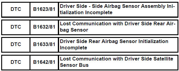
Toyota RAV4 (XA40) 2013-2018 Service Manual: Driver side - side airbag sensor assembly initialization incomplete
Description
The side airbag sensor lh consists of part including the diagnostic circuit and the lateral deceleration sensor.
When the center airbag sensor receives signals from the lateral deceleration sensor, it determines whether or not the srs should be activated.
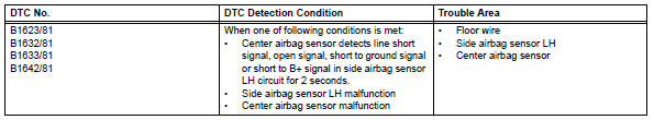
Dtc b1623/81, b1632/81, b1633/81 or b1642/81 is set when a malfunction is detected in the side airbag sensor lh circuit.
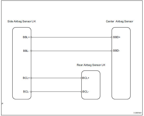
Wiring diagram
Inspection procedure
- Check connection of connector
- Turn the ignition switch off
- Disconnect the cable from the negative (-) battery terminal, and wait for at least 90 seconds.
- Check that the connectors are properly connected to the center airbag sensor , rear airbag sensor lh and the side airbag sensor lh.
Ok: the connectors are properly connected.


- Check floor wire (open)
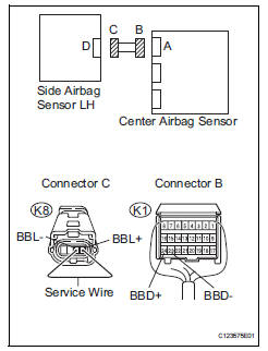
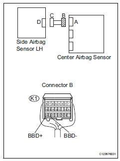
- Disconnect the connectors from the center airbag sensor and the side airbag sensor lh.
- Using a service wire, connect k8-4 (bbl+) and k8-3 (bbl-) of connector c.
Notice:
Do not forcibly insert the service wire into the terminals of the connector when connecting.
- Measure the resistance of the wire harness side connector.
Standard resistance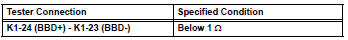

- Check floor wire (short)
- Disconnect the service wire from connector c.
- Measure the resistance of the wire harness side connector.
Standard resistance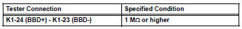


- Check floor wire (to b+)
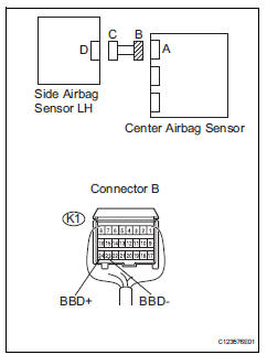
- Connect the cable to the negative (-) battery terminal, and wait for at least 2 seconds.
- Turn the ignition switch on.
- Measure the voltage of the wire harness side connector.
Standard voltage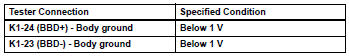


- Check floor wire (to ground)
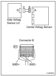
- Turn the ignition switch off.
- Disconnect the cable from the negative (-) battery terminal, and wait for at least 90 seconds.
- Measure the resistance of the wire harness side connector.
Standard resistance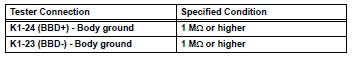

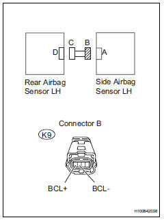
- Check floor wire (open)
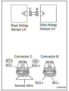
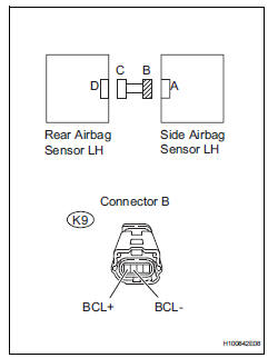
- Disconnect the connectors from the side airbag sensor lh and the rear airbag sensor lh.
- Using a service wire, connect k11-1 (bcl-) and k11-2 (bcl+) of connector c.
Notice:
Do not forcibly insert the service wire into the terminals of the connector when connecting.
- Measure the resistance of the wire harness side connector.
Standard resistance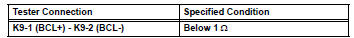


- Check floor wire (short)
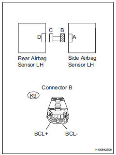
- Disconnect the service wire from connector c.
- Measure the resistance of the wire harness side connector.
Standard resistance 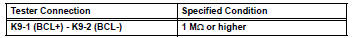

- V
- Connect the cable to the negative (-) battery terminal, and wait for at least 2 seconds.
- Turn the ignition switch on.
- Measure the voltage of the wire harness side connector.
Standard voltage 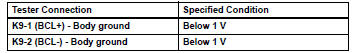

- Check floor wire (to ground)
- Turn the ignition switch off.
- Disconnect the cable from the negative (-) battery terminal, and wait for at least 90 seconds.
- Measure the resistance of the wire harness side connector.
Standard resistance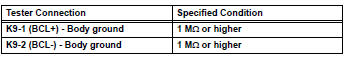

- Check side airbag sensor rh
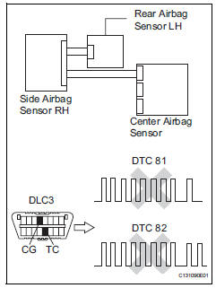
- Connect the connectors to the center airbag sensor.
- Interchange the side airbag sensor rh with the side airbag sensor lh and connect the connectors to them.
- Connect the cable to the negative (-) battery terminal, and wait for at least 2 seconds.
- Turn the ignition switch on, and wait for at least 60 seconds.
- Clear the dtcs (see page rs-49).
- Turn the ignition switch off
- Turn the ignition switch on, and wait for at least 60 seconds.
- Check for dtcs (see page rs-49).
Result 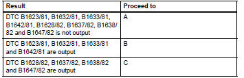
Hint:
Dtcs other than dtc b1623/81, b1632/81, b1633/81, b1642/81, b1628/82, b1637/82, b1638/82 and b1647/ 82 may be output at this time, but they are not relate to this check.

- Check rear airbag sensor rh
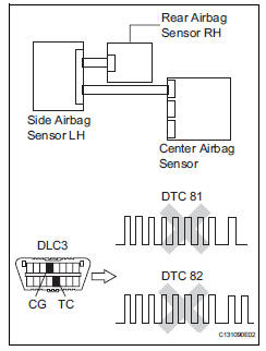
- Turn the ignition switch off.
- Disconnect the cable from the negative (-) battery terminal, and wait for at least 90 seconds.
- Interchange the rear airbag sensor rh with the rear airbag sensor lh and connect the connectors to them.
- Connect the cable to the negative (-) battery terminal, and wait for at least 2 seconds.
- Turn the ignition switch on, and wait for at least 60 seconds.
- Clear the dtcs (see page rs-49).
- Turn the ignition switch off.
- Turn the ignition switch on, and wait for at least 60 seconds.
- Check the dtcs (see page rs-49).
Result 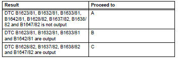
Hint:
Dtcs other than dtc b1623/81, b1632/81, b1633/81, b1642/81, b1628/82, b1637/82, b1638/82 and b1647/ 82 may be output at this time, but they are not relate to this check.

Use simulation method to check
 Lost communication with driver side - side airbag sensor assembly
Description
The side airbag sensor lh consists of part including the diagnostic circuit
and the lateral deceleration
sensor.
When the center airbag sensor receives signals from the lateral ...
 Front passenger side - side airbag sensor circuit malfunction
Description
The side airbag sensor rh consists of parts including the diagnostic circuit
and the lateral deceleration
sensor.
When the center airbag sensor receives signals from the lateral ...
Other materials:
System description
Engine immobiliser system description
The engine immobiliser system is designed to prevent
the vehicle from being stolen. This system uses a
transponder key ecu that stores the key codes of
authorized ignition keys. If an attempt is made to start
the engine using an unauthorized key, the e ...
Rear no. 1 Suspension arm
Components
Removal
Hint:
Use the same procedures for the rh side and lh side.
The procedures listed below are for the lh side.
Remove rear wheel
Remove rear no. 1 Suspension arm assembly lh
Support the no. 2 Suspension arm lh.
Remove the bolt and 2 nuts from t ...
Diagnosis system
Description
When troubleshooting obd ii (on-board diagnostics)
vehicles, the intelligent tester (complying with sae
j1987) must be connected to the dlc3 (data link
connector 3) of the vehicle. Various data in the vehicle's
ecm (engine control module) can be then read.
Obd ii regulations ...
