Toyota RAV4 (XA40) 2013-2018 Service Manual: Front passenger side - side airbag sensor circuit malfunction

Description
The side airbag sensor rh consists of parts including the diagnostic circuit and the lateral deceleration sensor.
When the center airbag sensor receives signals from the lateral deceleration sensor, it determines whether or not the srs should be activated.
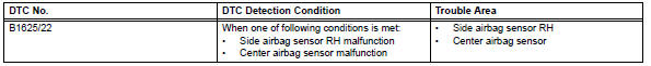
Dtc b1625/22 is set when a malfunction is detected in the side airbag sensor rh circuit.
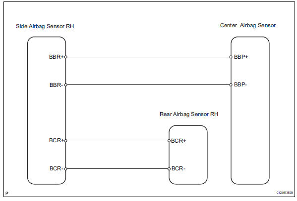
Wiring diagram
Inspection procedure
- Check side airbag sensor rh
- Turn the ignition switch off.
- Disconnect the cable from the negative (-) battery terminal, and wait for at least 90 seconds.
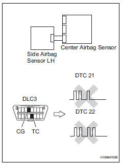
- Interchange the side airbag sensor rh and the side airbag sensor lh, and connect the connectors to them.
- Connect the cable to the negative (-) battery terminal, and wait for at least 2 seconds.
- Turn the ignition switch on, and wait for at least 60 seconds.
- Clear the dtcs (see page rs-49).
- Turn the ignition switch off.
- Turn the ignition switch on, and wait for at least 60 seconds.
- Check the dtcs (see page rs-49).
Result 
Dtcs other than dtc b1620/21 and b1625/22 may be output at this time, but they are not related to this check.


Use simulation method to check
 Driver side - side airbag sensor assembly initialization incomplete
Description
The side airbag sensor lh consists of part including the diagnostic circuit
and the lateral deceleration
sensor.
When the center airbag sensor receives signals from the lateral ...
 Lost communication with front passenger side - side airbag sensor assembly
Description
The side airbag sensor rh consists of parts including the diagnostic circuit
and the lateral deceleration
sensor.
When the center airbag sensor receives signals from the lateral ...
Other materials:
Seat heater system
Parts location
System diagram
Problem symptoms table
Hint:
Use the table below to help determine the cause of the
problem symptom. The potential causes of the symptoms are
listed in order of probability in the "suspected area" column
of the table. Check each symptom by check ...
Abs warning light does not come on
Wiring diagram
Refer to the abs warning light circuit (see page bc-135).
Inspection procedure
Check can communication system
Check if the can communication system dtc is output
(see page ca-34).
Result
Perform active test by intelligent tester (abs warning light)
Sele ...
Cleaning and protecting the vehicle interior
Perform cleaning in a manner
appropriate to each
component and its material.
Protecting the vehicle
interior
Remove dirt and dust using a
vacuum cleaner. Wipe dirty
surfaces with a cloth dampened
with lukewarm water.
If dirt cannot be removed,
wipe it off with a soft cloth
dampened with neut ...
