Toyota RAV4 (XA40) 2013-2018 Service Manual: Dtc check / clear
- Check dtc
- Dtcs which are stored in the ecm can be displayed
with the intelligent tester.
The intelligent tester can display pending dtcs and current dtcs. Some dtcs are not stored unless a malfunction is detected in consecutive driving cycles. When a malfunction is detected in only one driving cycle, it is stored as a pending dtc.
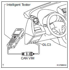
- Connect the intelligent tester to the can vim.
Then connect the can vim to the dlc3.
- Turn the ignition switch on and turn the tester on.
- Enter the following menus: diagnosis / enhanced obd ii / dtc info / current codes (or pending code).
- Confirm the dtcs and freeze frame data and then write them down.
- Confirm the details of the dtcs (see page ax- 35).
Notice:
When simulating a symptom with the scan tool to check for dtcs, use normal mode.
For codes on the diagnostic trouble code chart subject to "2 trip detection logic", perform the following actions.
Turn the ignition switch off after the symptom is simulated once. Then repeat the simulation process again. When the symptom has been simulated twice, the mil illuminates and the dtcs are recorded in the ecm.
- Clear dtc
- When using the intelligent tester:
- Connect the intelligent tester to the can vim.
Then connect the can vim to the dlc3.
- Turn the ignition switch on and turn the tester on.
- Enter the following menus: diagnosis / enhanced obd ii / dtc info / clear codes. Then and press yes.
Hint:
When operating the tester to erase the codes, the dtcs and freeze frame data will be erased.
- When not using the intelligent tester:
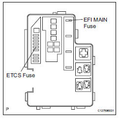
- Disconnect the battery terminal or remove the efi main and etcs fuses from the engine room no. 1 Relay block and engine room no. 1 Junction block for 60 seconds or more. However, if you disconnect the battery terminal, perform the "initialization" procedure (see page ax- 18).
 Diagnosis system
Description
When troubleshooting on-board diagnostic (obd
ii) vehicles, the vehicle must be connected to the
obd ii scan tool (complying with sae j1987).
Various data output from the ...
 Check mode procedure
Description
Check mode has a higher sensitivity to malfunctions
and can detect malfunctions that normal mode
cannot detect. Check mode can also detect all the
malfunctions that normal m ...
Other materials:
Front seats
The seats can be adjusted
(longitudinally, vertically,
etc.). Adjust the seat to
ensure the correct driving
posture.
Adjustment procedure
Manual seat
Seat position adjustment
lever
Seatback angle adjustment
lever
Vertical height adjustment
lever (driver's side only)
Power seat
Seat posit ...
Downhill assist control system
The downhill assist control
system helps to prevent
excessive speed on steep
downhill slopes.
The system will operate
when the vehicle is traveling
under 15 mph (25 km/h) with
the accelerator and brake
pedals released.
WARNING
â– When using downhill assist
control system
Do not rely overmuch on the ...
Parts location
System diagram
The configuration of the electronic control system in the
u140f automatic transaxle is as shown in the following chart.
System description
System description
The electronic controlled automatic transaxle
(ect) is an automatic transaxle that elect ...
