Toyota RAV4 (XA40) 2013-2018 Service Manual: Check mode procedure
- Description
- Check mode has a higher sensitivity to malfunctions and can detect malfunctions that normal mode cannot detect. Check mode can also detect all the malfunctions that normal mode can detect. In check mode, dtcs are detected with 1 trip detection logic.
- Check mode procedure
- Make sure that the following conditions below are met:
- Battery positive voltage 11 v or more
- Throttle valve fully closed
- Transaxle in the p or n position
- A/c off
- Turn the ignition switch off.
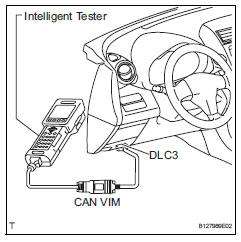
- Connect the intelligent tester to the can vim. Then connect the can vim to the dlc3.
- Turn the ignition switch on and turn the tester on.
- Enter the following menus: diagnosis / enhanced obd ii / check mode.
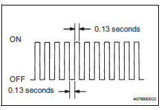
- Change the ecm to check mode. Make sure the mil flashes as shown in the illustration.
Notice:
All dtcs and freeze frame data recorded will be erased if: 1) the intelligent tester is used to change the ecm from normal mode to check mode or vice versa; or 2) during check mode, the ignition switch is turned from on to acc or off.
Before check mode, make notes of the dtcs and freeze frame data.
- Start the engine. The mil should turn off after the engine starts.
- Perform "monitor drive pattern" for the ect
test (see page ax-19).
(Or, simulate the conditions of the malfunction described by the customer.)
- After simulating the malfunction conditions, use the tester to check the dtc and freeze frame data.
 Dtc check / clear
Check dtc
Dtcs which are stored in the ecm can be displayed
with the intelligent tester.
The intelligent tester can display pending dtcs and
current dtcs. Some dtcs are not stored ...
 Fail-safe chart
Fail-safe chart
This function minimizes the loss of the ect functions
when a malfunction occurs in a sensor or solenoid.
Automatic transmission fluid (atf) temperature
sensor:
when the ...
Other materials:
Fastening the seat belt (for the rear center seat)
Press the plate to release, and
then pull the seat belt.
Push the plate into the buckle in
the order of plate “a” and plate
“b” until a clicking sound is
heard.
Plate “a”, buckle “a”
Plate “b”, buckle “b”
...
Compressor solenoid circuit (2005/11-2006/01)
Description
In this circuit, the compressor receives a refrigerant compression demand
signal from the air conditioning
amplifier. Based on this signal, the compressor changes the degree of
refrigerant compression.
Wiring diagram
Inspection procedure
Read value of intelligent ...
Parking Support Brake
function (rear-crossing
vehicles)
If a rear radar sensor detects a vehicle approaching from the
right or left at the rear of the vehicle and the system determines
that the possibility of a collision is high, this function
will perform brake control to reduce the likelihood of an
impact with the approaching vehicle.
Examples of funct ...
