Toyota RAV4 (XA40) 2013-2018 Service Manual: Electronic control
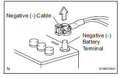
- Removal and installation of battery terminal
Notice:
Certain systems need to be initialized after disconnecting and reconnecting the cable from the negative (-) battery terminal.
- Before performing electronic work, disconnect the cable from the negative (-) battery terminal to prevent component and wire damage caused by accidental short circuits.
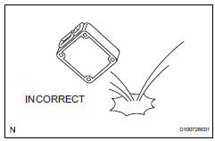
- When disconnecting the cable, turn the ignition switch off and headlight dimmer switch off and loosen the cable nut completely. Perform these operations without twisting or prying the cable. Then disconnect the cable.
- Clock settings, radio settings, audio system memory, dtcs and other data are erased when the cable is disconnected from the negative (-) battery terminal. Write down any necessary data before disconnecting the cable.
- Handling of electronic parts
- Do not open the cover or case of the ecu unless absolutely necessary. If the ic terminals are touched, the ic may be rendered inoperative by static electricity.
- Do not pull the wires when disconnecting electronic connectors. Pull the connector.
- Be careful not to drop electronic components, such as sensors or relays. If they are dropped on a hard surface, they should be replaced.
- When cleaning the engine with steam, protect the electronic components, air filter and emission-related components from water.
- Never use an impact wrench to remove or install temperature switches or temperature sensors.
- When measuring the resistance of a wire connector, insert the tester probe carefully to prevent terminals from bending.
 For vehicles with supplemental restraint system
The rav4 is equipped with a supplemental restraint
system (srs). The srs of this vehicle consists of the
following:
Steering pad
Front passenger airbag assembly
Front seat side airbag assemb ...
 Removal and installation of fuel control
parts
Removal and installation of fuel control
parts
Place for removing and installing fuel
system parts
Work in a location with good air ventilation that
does not have welders, grinders, drills, electric
motors, stoves, or any other igni ...
Other materials:
Short in can bus lines
Description
There may be a short circuit between the can bus lines when the resistance
between terminals 6 (canh)
and 14 (canl) of the dlc3 is below 54
.
Wiring diagram
Inspection procedure
Notice:
Turn the ignition switch off before measuring the resistances of the
main ...
Front power seat lumbar switch
Inspection
Inspect front power seat lumbar switch lh
Measure the resistance between the terminals when
the switch is operated.
Standard resistance
If the result is not as specified, replace the switch. ...
Tire rotation
Rotate the tires in the order
shown.
To equalize tire wear and extend
tire life, Toyota recommends that
tire rotation is carried out at the
same interval as tire inspection.
Do not fail to initialize the tire pressure
warning system after tire rotation.
(if equipped)
Front
â– When rotating th ...
