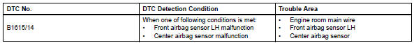
Toyota RAV4 (XA40) 2013-2018 Service Manual: Front airbag sensor lh circuit malfunction
Description
The front airbag sensor lh consists of the diagnostic circuit, the frontal deceleration sensor, etc.
If the center airbag sensor receives signals from the frontal deceleration sensor, it determines whether or not the srs should be activated.
Dtc b1615/14 is recorded when a malfunction is detected in the front airbag sensor lh circuit.
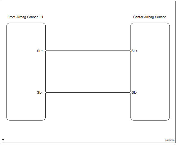
Wiring diagram
Inspection procedure
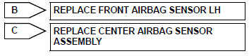
- Check front airbag sensor lh
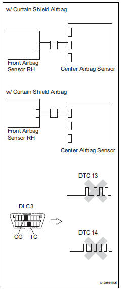
- Turn the ignition switch off.
- Disconnect the cable from the negative (-) battery terminal, and wait for at least 90 seconds.
- Interchange the front airbag sensor rh and lh, and connect the connectors to them.
- Connect the cable to the negative (-) battery terminal, and wait for at least 2 seconds.
- Turn the ignition switch on, and wait for at least 60 seconds.
- Clear the dtcs (see page rs-49).
- Turn the ignition switch off
- Turn the ignition switch on, and wait for at least 60 seconds.
- Check the dtcs (see page rs-49).
Result 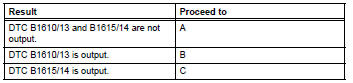
Hint:
Dtcs other than dtc b1610/13 and b1615/14 may be output at this time, but they are not related to this check.

Use simulation method to check
 Front airbag sensor rh circuit malfunction
Description
The front airbag sensor rh consists of the diagnostic circuit, the frontal
deceleration sensor, etc.
If the center airbag sensor assembly receives signals from the frontal
dece ...
 Driver side - side airbag sensor circuit malfunction
Description
The side airbag sensor lh consists of part including the diagnostic circuit
and the lateral deceleration
sensor.
When the center airbag sensor receives signals from the lateral ...
Other materials:
Reassembly
Hint:
When installing the ornament plate and emblem, heat the
radiator grille, ornament plate and emblem using a heat light.
Standard heating temperature
Notice:
Do not heat the emblem base and emblem excessively.
Install radiator grille emblem
Attach the 4 claws to install the radi ...
Master cylinder pressure sensor malfunction
Description
The master cylinder pressure sensor is connected to the skid control ecu in
the abs and traction
actuator.
Dtc c1281/81 can be detected when the master cylinder pressure sensor sends a
master cylinder
pressure signal or test mode ends. Dtc c1281/81 is output only in test mo ...
Terminals of ecu
Check power steering ecu
Hint:
Measurements cannot be performed on the c connector
side of the power steering ecu.
Measure the voltage and resistance of the
connectors.
If the result is not as specified, the ecu may have a
malfunction. ...
