Toyota RAV4 (XA40) 2013-2018 Service Manual: Installation
- Install fuel filler opening lid lock retainer
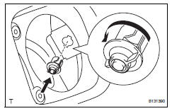
- Install the lock retainer and turn it counterclockwise as shown in the illustration.
- Install fuel filler opening lid lock retainer
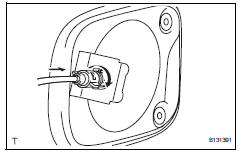
- Install the cable and turn it clockwise as shown in the illustration.
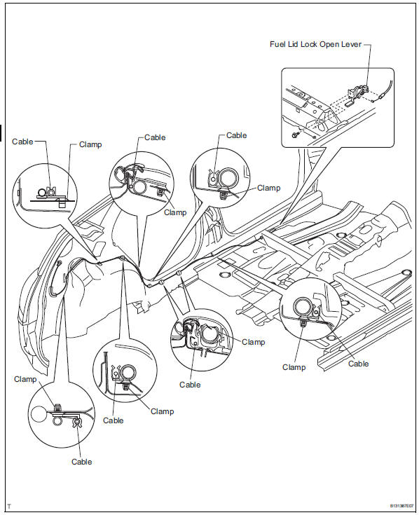
- Install the fuel lid lock open lever with the bolt.
Torque: 8.0 N*m (82 kgf*cm, 71 in.*Lbf)
- Install the cable to the clamps as shown in the illustration.
- Install front floor carpet assembly
- Install deck trim side panel assembly rh (w/ rear no. 2 Seat) (see page ir-34)
- Install deck trim side panel assembly rh (w/o rear no. 2 Seat) (see page ir-53)
- Install deck trim side panel assembly lh (w/ rear no. 2 Seat) (see page ir-32)
- Install deck trim side panel assembly lh (w/ o rear no. 2 Seat) (see page ir-52)
- Install tether anchor bracket subassembly (w/o rear no. 2 Seat) (see page ir-54)
- Install reclining remote control lever bezel rh (w/o rear no. 2 Seat) (see page se-105)
- Install reclining remote control lever bezel lh (w/o rear no. 2 Seat) (see page se-73)
- Install rear deck trim cover rh (w/ rear no.
2 Seat) (see page ir-55)
- Install rear deck trim cover lh (w/ rear no.
2 Seat) (see page ir-55)
- Install rear floor finish plate (see page ir- 55)
- Install back door weatherstrip
- Install rear floor no. 1 Mat support side plate (see page ir-55)
- Install rear floor no. 2 Board
- Install rear floor no. 3 Board
- Install rear no. 2 Seat assembly rh (w/ rear no. 2 Seat)
- Install the rear no. 2 Seat (see page se-121).
- Install rear no. 2 Seat assembly lh (w/ rear no. 2 Seat)
- Install the rear no. 2 Seat (see page se-121).
- Install deck board assembly (w/o rear no. 2 Seat)
- Install rear floor no. 1 Board (w/o rear no.
2 Seat)
- Install rear floor no. 1 Board (w/o rear no.
2 Seat)
- Install package tray trim pocket subassembly (w/o rear no. 2 Seat)
- Install lower center pillar garnish rh (see page ir-56)
- Install lower center pillar garnish lh (see page ir-56)
- Install rear door opening trim weatherstrip rh
- Install rear door opening trim weatherstrip lh
- Install rear door scuff plate rh (see page ir-57)
- Install rear door scuff plate lh (see page ir-57)
- Install front door opening trim weatherstrip rh
- Install front door opening trim weatherstrip lh
- Install cowl side trim board rh (see page ir- 59)
- Install cowl side trim board lh (see page ir- 59)
- Install front door scuff plate rh (see page ir-59)
- Install front door scuff plate lh (see page ir-59)
- Install rear console box sub-assembly (see page ip-26)
- Install rear console box sub-assembly (see page ip-26)
- Install rear console box sub-assembly (see page ip-26)
- Install rear console box sub-assembly (see page ip-26)
- Install upper rear console panel subassembly (see page ip-27)
- Install upper rear console panel subassembly (see page ip-27)
- Install switch base (see page ip-27)
- Install upper console panel sub-assembly (see page ip-27)
- Install no. 2 Console upper panel garnish (see page ip-28)
- Install no. 1 Console upper panel garnish (see page ip-28)
- Install rear no. 1 Seat assembly lh
- Install the rear no. 1 Seat (see page se-64).
- Install rear no. 1 Seat assembly rh
- Install the rear no. 1 Seat (see page se-97).
- Install front seat assembly lh
- Install the front seat.
For manual seat (see page se-22) for power seat (see page se-37).
- Install front seat assembly rh
- Install the front seat.
For manual seat (see page se-22) for power seat (see page se-37)
- Connect cable to negative battery terminal
- Check srs warning light
- Check the srs warning light (see page rs-37).
 Removal
Disconnect cable from negative battery
terminal
Caution:
Wait at least 90 seconds after disconnecting the
cable from the negative (-) battery terminal to
prevent airbag and seat belt preten ...
 Exterior
...
Other materials:
System description
General
The front passenger occupant classification system
judges whether the front passenger seat is occupied
or not in accordance with the seat belt buckle
status; and whether the seat is occupied by an adult
or child (with child seat) in accordance with the load
that is applied ...
Circuit opening relay
On-vehicle inspection
Disconnect cable from negative battery
terminal
Caution:
Wait at least 90 seconds after disconnecting the
cable from the negative (-) battery terminal to
prevent airbag and seat belt pretensioner activation.
Inspect instrument panel junction block
Notice:
Th ...
Front seatback heater
Inspection
Inspect front seatback heater assembly
lh
Measure the resistance of the seatback heater.
Standard resistance
If the result is not as specified, replace the seatback
heater assembly
Inspect front seatback heater assembly
rh
Hint:
Use the same procedures desc ...
