Toyota RAV4 (XA40) 2013-2018 Service Manual: Removal
- Disconnect cable from negative battery terminal
Caution:
Wait at least 90 seconds after disconnecting the cable from the negative (-) battery terminal to prevent airbag and seat belt pretensioner activation.
- Remove front seat assembly lh
- Remove the front seat.
For manual seat (see page se-11) for power seat (see page se-27)
- Remove front seat assembly rh
- Remove the front seat.
For manual seat (see page se-11) for power seat (see page se-27)
- Remove rear no. 1 Seat assembly lh
- Remove the rear no. 1 Seat (see page se-45).
- Remove rear no. 1 Seat assembly rh
- Remove the rear no. 1 Seat (see page se-80).
- Remove no. 1 Console upper panel garnish (see page ip-17)
- Remove no. 2 Console upper panel garnish (see page ip-18)
- Remove upper console panel sub-assembly (see page ip-18)
- Remove switch base (see page ip-18)
- Remove console cup holder box (see page ip-18)
- Remove upper rear console panel subassembly (see page ip-19)
- Remove console rear end panel (see page ip- 19)
- Remove no. 1 Instrument panel bracket cover inner lh (see page ip-19)
- Remove no. 1 Instrument panel bracket cover inner rh (see page ip-19)
- Remove rear console box sub-assembly (see page ip-20)
- Remove front door scuff plate lh (see page ir-26)
- Remove front door scuff plate rh (see page ir-26)
- Remove cowl side trim board lh (see page ir- 26)
- Remove cowl side trim board rh (see page ir-26)
- Remove front door opening trim weatherstrip lh
- Remove front door opening trim weatherstrip rh
- Remove rear door scuff plate lh (see page ir-29)
- Remove rear door scuff plate rh (see page ir-29)
- Remove rear door opening trim weatherstrip lh
- Remove rear door opening trim weatherstrip rh
- Remove lower center pillar garnish lh (see page ir-29)
- Remove lower center pillar garnish rh (see page ir-30)
- Remove package tray trim pocket subassembly (w/o rear no. 2 Seat)
- Remove tonneau cover assembly (w/o rear no. 2 Seat)
- Remove rear floor no. 1 Board (w/o rear no.
2 Seat)
- Remove deck board assembly (w/o rear no. 2 Seat)
- Remove rear no. 2 Seat assembly lh (w/ rear no. 2 Seat)
- Remove the rear no. 2 Seat (see page se-109).
- Remove rear no. 2 Seat assembly rh (w/ rear no. 2 Seat)
- Remove the rear no. 2 Seat (see page se-109).
- Remove rear floor no. 3 Board
- Remove rear floor no. 2 Board
- Remove rear floor no. 1 Mat support side plate (see page ir-31)
- Remove back door weatherstrip
- Remove rear floor finish plate (see page ir- 31)
- Remove rear deck trim cover lh (w/ rear no.
2 Seat) (see page ir-31)
- Remove rear deck trim cover lh (w/ rear no.
2 Seat) (see page ir-31)
- Remove reclining remote control lever bezel lh (w/o rear no. 2 Seat) (see page se-45)
- Remove reclining remote control lever bezel rh (w/o rear no. 2 Seat) (see page se-80)
- Remove tether anchor bracket subassembly (w/o rear no. 2 Seat) (see page ir-32)
- Remove deck trim side panel assembly lh (w/o rear no. 2 Seat) (see page ir-32)
- Remove deck trim side panel assembly lh (w/ rear no. 2 Seat) (see page ir-32)
- Remove deck trim side panel assembly lh (w/ rear no. 2 Seat) (see page ir-32)
- Remove deck trim side panel assembly rh (w/ rear no. 2 Seat) (see page ir-34)
- Remove front floor carpet assembly
- Partially remove the floor carpet.
Hint:
It is not necessary to fully remove the floor carpet.
Partially remove it so that the lock control cable can be removed in a later step.
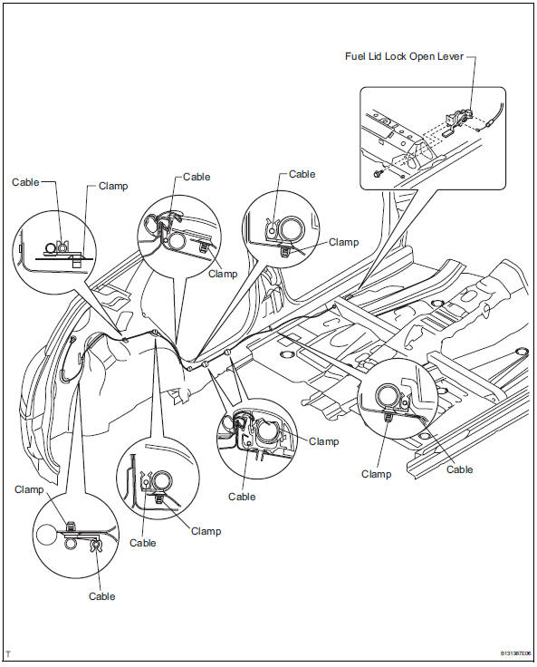
- Remove fuel lid lock control cable subassembly
- Remove the bolt and fuel lid lock open lever.
- Remove the tape and cable from the clamps as shown in the illustration.
- Remove fuel lid lock control cable subassembly
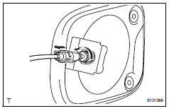
- Remove fuel filler opening lid lock retainer
- Turn the lock retainer clockwise and remove the lock retainer as shown in the illustration.
 Components
...
 Installation
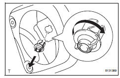
Install fuel filler opening lid lock retainer
Install the lock retainer and turn it counterclockwise
as shown in the illustration.
Install fuel filler opening lid lock retainer
...
Other materials:
Outer mirror switch
Inspection
Inspect outer mirror switch assembly
The l position of the left/right adjustment switch:
measure the resistance of the mirror switch.
Standard resistance (for left side)
If the result is not as specified, replace the switch
assembly.
The r position of the left/r ...
Garage door opener
The garage door opener can
be programmed using the
HomeLink to operate
garage doors, gates, entry
doors, door locks, home
lighting systems, security
systems, and other devices.
â– HomeLink programming procedure
The programming procedures can
also be found at the following URL.
System components
The ...
General maintenance (2006/01- )
General notes
Maintenance requirements vary depending on the
country.
Check the maintenance schedule in the owner's
manual supplement.
Following the maintenance schedule is mandatory.
Determine the appropriate time to service the vehicle
using either miles driven or time elapsed ...
