
Toyota RAV4 (XA40) 2013-2018 Service Manual: Parts location
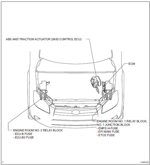
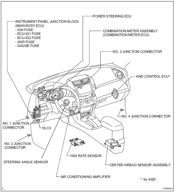
System diagram
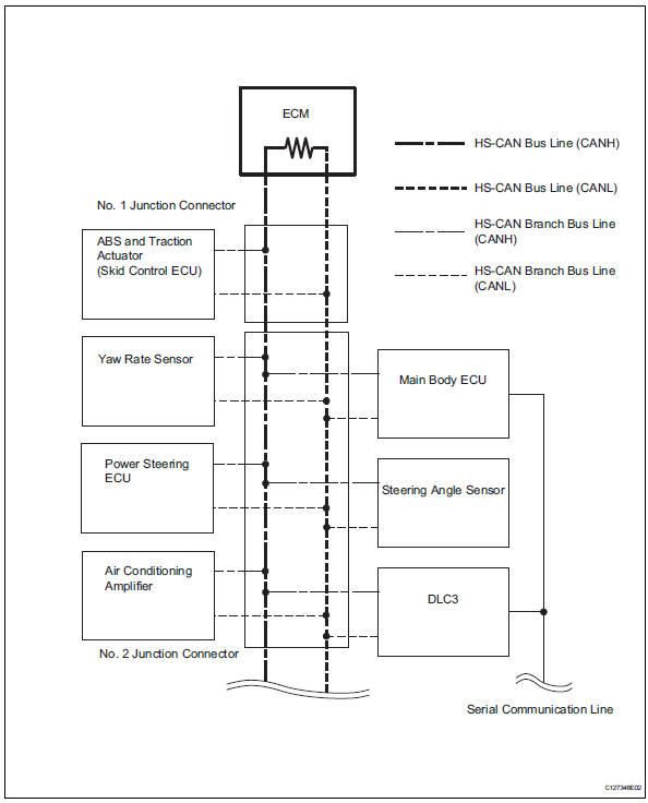
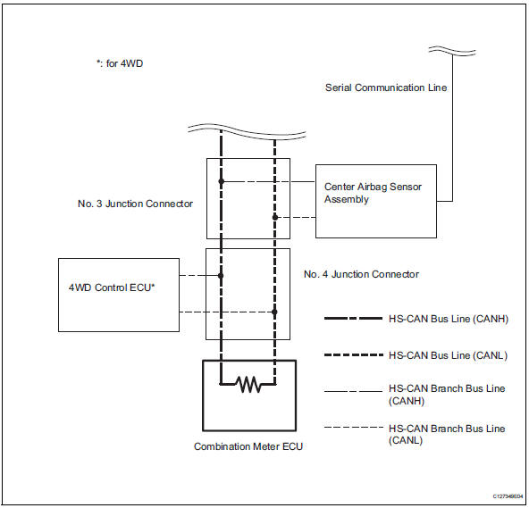
Hint:
- The abs and traction actuator (skid control ecu) detects and stores steering sensor and yaw rate sensor dtcs and performs dtc communication by receiving information from the steering sensor and yaw rate sensor.
- The ecm uses the can communication system to perform dtc communication instead of the conventional communication line (sil).
 Can communication system
Precaution
Precaution
Turn the ignition switch off before measuring the
resistance of the main wire and the branch wire.
After the ignition switch is turned off, check that the
key rem ...
 System description
Brief description
The can (controller area network) is a serial data
communication system for real time application. It is
a vehicle multiplex communication system which
has a high comm ...
Other materials:
Seat position sensor
Components
On-vehicle inspection
Check seat position sensor (vehicle not
involved in collision)
Perform a diagnostic system check (see page rs-
49).
Check seat position sensor (vehicle
involved in collision)
Perform a diagnostic system check (see page rs-
49).
Ev ...
Installation
Hint:
Use the same procedures for the rh side and lh side.
The procedures listed below are for the lh side.
Install rear door belt moulding assembly
lh
Attach the claws to install the moulding.
Hint:
Confirm that the moulding is firmly installed.
Install rear door tr ...
Air mix damper control servo motor circuit (driver
side)
Description
The air mix damper servo sends pulse signals to indicate the damper position
to the air conditioning
amplifier. The air conditioning amplifier activates the motor (normal or
reverse) based on these signals to
move the air mix damper (driver seat) to the appropriate position. T ...
