Toyota RAV4 (XA40) 2013-2018 Service Manual: Installation
- Install upper instrument panel
- Attach the 6 clips and 5 claws to install the instrument panel.
- Connect the connectors and clamps.
- Install the 2 bolts and 2 screws.
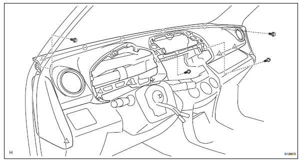
- Connect the passenger airbag connector.
- Install the 2 bolts to the passenger airbag.
Torque: 20 n*m (204 kgf*cm, 15 ft.*Lbf)
- Install front pillar garnish lh (see page ir- 57)
- Install front pillar garnish rh (see page ir- 58)
- Install glove compartment door assembly (see page ip-25)
- Install instrument panel register assembly center
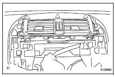
- Attach the 5 clips to install the instrument panel register.
- Install radio receiver
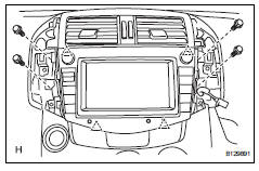
- Connect the connectors.
- Attach the 4 clips to install the radio receiver.
- Install the 4 bolts.
- Install no. 1 Instrument cluster finish panel center
- Connect the connector.
- Attach the 3 clips and 3 claws to install the cluster finish panel.
- Install no. 2 Instrument cluster finish panel center
- Connect the connector.
- Attach the 3 clips and 3 claws to install the cluster finish panel.
- Install combination meter assembly
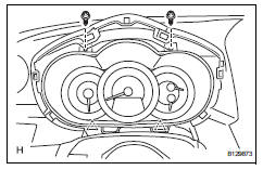
- Connect the connector.
- Attach the 2 clips to install the combination meter.
- Install the 2 screws.
- Install instrument cluster finish panel sub-assembly
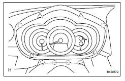
- Attach the 4 clips and 6 claws to install the instrument cluster finish panel.
- Connect cable to negative battery terminal
- Check srs warning light
- Check the srs warning light (see page rs-37).
 Reassembly
Install cooler (solar sensor) thermistor
(for automatic air conditioning system)
Install automatic light control sensor
(for automatic light control system)
Install front passenger airbag a ...
 Lower instrument panel
Precaution
Precaution for vehicle with srs airbag and
seat belt pretensioner
Some operations in this section may affect the srs
airbags and seat belt pretensioner. Prior to
performing ...
Other materials:
Valve clearance
Adjustment
Disconnect cable from negative battery
terminal
Caution:
Wait at least 90 seconds after disconnecting the
cable from the negative (-) battery terminal to
prevent airbag and seat belt pretensioner activation.
Remove front wheel rh
Remove no. 1 Engine under cover
Remove ...
System description
Lighting system
Illumination control system (illuminated entry
system):
When the doors are unlocked by a key or
transmitter operation, or when a door is opened or
closed, the illuminated entry system turns on the
room light, map light, foot light and ignition key
cylinder light*1 o ...
Parking brake cable
Components
Removal
Remove rear console box sub-assembly
Remove the rear console box (see page ip-16).
Hint:
Refer to the procedures from the removal of the no.
1 Console upper panel garnish up until the removal
of the rear console box sub-assembly.
Loosen lock nut and no. ...
