Toyota RAV4 (XA40) 2013-2018 Service Manual: Installation
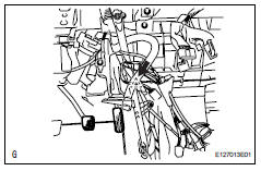
- Install air conditioner unit assembly
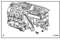
- Install the a/c unit with the bolt and nut.
Torque: 9.8 N*m (100 kgf*cm, 7 ft.*Lbf)
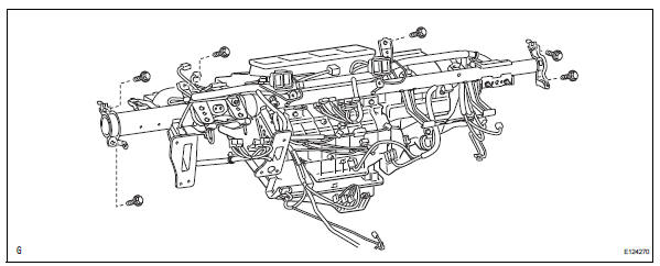
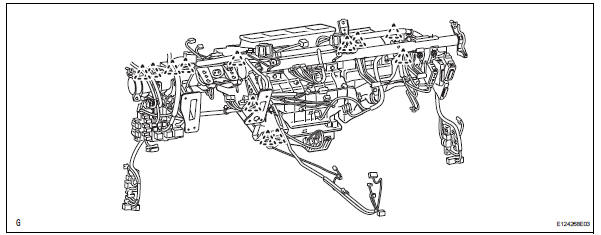
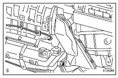
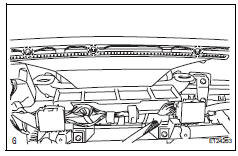
- Install instrument panel reinforcement
- Install the instrument panel reinforcement with the 6
bolts.
Torque: 20 n*m (204 kgf*cm, 15 ft.*Lbf)
- Install the 3 bolts.
Torque: 9.8 N*m (100 kgf*cm, 7 ft.*Lbf)
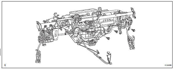
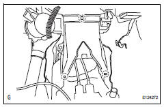
- Install the 4 bolts and connect the ground wire.
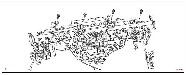
- Attach the 12 clamps.
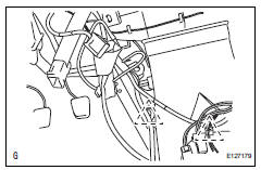
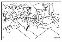
- Install drain cooler hose
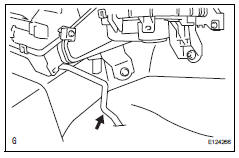
- Install the drain hose.
- Install air conditioning amplifier assembly
- Install the a/c amplifier with the screw.
- Connect the connector.
- Attach the 2 clamps to the amplifier.
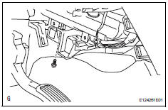
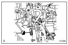
- Install air duct
- Attach the 2 claws and install the air duct.
- Install rear air duct
- Attach the 3 claws and install the air duct rear.
- Attach the 2 clamps and install the wire harness.
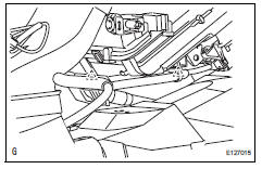
- Install no. 1 Instrument panel brace subassembly
- Install the instrument panel brace with the bolt, nut and screw.
- Install the clamp and connect the wire harness.
- Reposition the floor carpet.
- Install defroster nozzle assembly
- Attach the 3 claws and install the defroster nozzle assembly lower.
- Install lower instrument panel
- Install the lower instrument panel (see page ip-23).
- Install upper instrument panel
- Install the upper instrument panel (see page ip-9).
- Install steering column assembly
- Install the steering column (see page sr-19).
- Connect heater water outlet hose
- Connect the water hose and attach the clip.
- Connect heater water inlet hose
Hint:
Use the same procedures described for the water outlet hose.
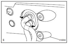
- Connect tube sub-assembly
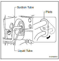
- Remove the attached vinyl tape from the pipe.
- Sufficiently apply compressor oil to new 2 o-rings and the fitting surface of the suction tube and liquid tube.
Compressor oil: nd-oil 8 or equivalent
- Install the 2 o-rings on the suction tube and liquid tube.
- Connect the suction tube and liquid tube.
Hint:
After the connection, check that the claw of the piping clamp is engaged.
- Install the plate with the bolt.
Torque: 9.8 N*m (100 kgf*cm, 7 ft.*Lbf)
- Connect cable to negative battery terminal
- Check srs warning light
- Check the srs warning light (see page rs-37).
- Replace engine coolant refer to the following procedures (see page co-6).
- Charge refrigerant (see page ac-172)
- Warm up engine (see page ac-173)
- Check for engine coolant leaks
- Check for leakage of refrigerant (see page ac-173)
 Reassembly
Install evaporator temperature sensor
Notice:
If reusing the evaporator, do not insert the sensor to
a location where the sensor was previously inserted.
Insert the sensor within range c sh ...
 Blower unit
Components
Removal
Disconnect cable from negative battery
terminal
Caution:
Wait at least 90 seconds after disconnecting the
cable from the negative (-) battery terminal to
prevent ai ...
Other materials:
Abs warning light does not come on
Wiring diagram
Refer to the abs warning light circuit (see page bc-135).
Inspection procedure
Check can communication system
Check if the can communication system dtc is output
(see page ca-34).
Result
Perform active test by intelligent tester (abs warning light)
Sele ...
Multi-information display
Display contents
The multi-information display presents the driver with a variety of driving-
related data including the current outside air temperature.
Outside temperature display
Indicates the outside temperature.
The temperature range that can be
displayed is from -40„af (-40„ac) t ...
Using the interior lights
Interior lights list
Interior lights
Interior/personal lights
Engine switch light (if equipped)
Cup holder light (if equipped)
Interior lights
Front
Off
Door position
The interior lights come on when
a door is opened. They turn off
when the doors are closed.
On
...
