Toyota RAV4 (XA40) 2013-2018 Service Manual: Blower unit
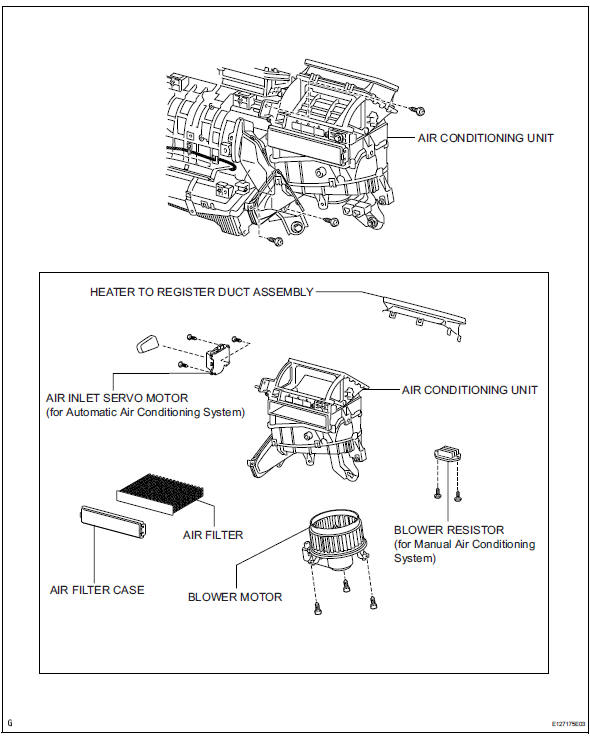
Components
Removal
- Disconnect cable from negative battery terminal
Caution:
Wait at least 90 seconds after disconnecting the cable from the negative (-) battery terminal to prevent airbag and seat belt pretensioner activation.
- Remove upper instrument panel
- Remove the upper instrument panel (see page ip- 4).
- Remove lower instrument panel
- Remove the lower instrument panel (see page ip- 16).
- Remove air duct (see page ac-188)
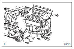
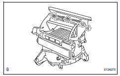
- Remove air conditioning unit
- Remove the air conditioning unit (see page ac- 185).
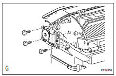
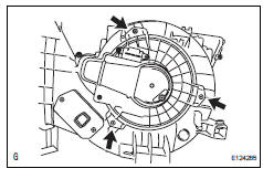
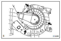
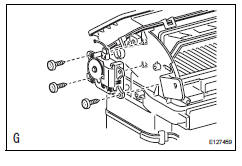
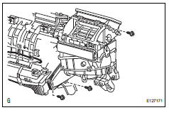
- Remove blower assembly
- Remove the 3 screws and blower.
Disassembly
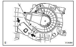
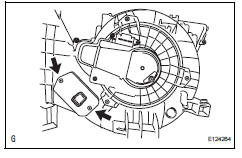
- Remove heater to register duct assembly
- Detach the 7 claws and register duct.
- Remove air filter case
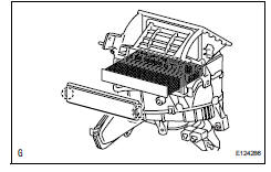
- Detach the 2 claws and remove the air filter case.
- Remove the air filter.
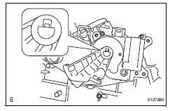
- Remove air inlet control servo motor (for manual air conditioning system)
- Remove the 3 screws and air inlet servo motor.
- Remove air inlet control servo motor (for automatic air conditioning system)
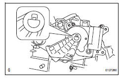
- Detach the claws and lever.
- Remove the 3 screws and air inlet servo motor.
- Remove blower resistor (for manual air conditioning system)
- Remove the 2 screws and blower resistor.
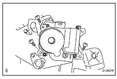
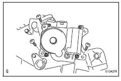
- Remove blower motor
- Remove the 3 screws and blower motor.
Reassembly
- Install blower motor
- Install the blower motor with the 3 screws.
- Install blower resistor (for manual air conditioning system)
- Install the blower resistor with the 2 screws.
- Install air inlet control servo motor (for automatic air conditioning system)
- Install the air inlet servo motor with the 3 screws.
- Attach the claw to install the lever.
- Install air inlet control servo motor (for manual air conditioning system)
- Install the air inlet servo motor with the 3 screws.
- Install air filter case
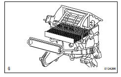
- Install the air filter.
- Attach the 2 claws to install the air filter case.
- Install heater to register duct assembly
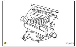
- Attach the 7 claws to install the register duct.
Installation
- Install blower assembly
- Install the blower assembly with the 3 screws.
- Install air conditioning unit
- Install the air conditioning unit (see page ac-197).
- Install air duct (see page ac-199)
- Install lower instrument panel
- Install the lower instrument panel (see page ip-23).
- Install upper instrument panel
- Install the upper instrument panel (see page ip-9).
- Connect cable to negative battery terminal
- Check srs warning light
- Check the srs warning light (see page rs-37).
 Installation
Install air conditioner unit assembly
Install the a/c unit with the bolt and nut.
Torque: 9.8 N*m (100 kgf*cm, 7 ft.*Lbf)
Install instrument panel reinforcement
Install th ...
 Blower motor
On-vehicle inspection
Inspect blower motor (for automatic air conditioning system)
Disconnect the blower motor connector.
Connect the positive (+) lead from the battery to
terminal 1 ...
Other materials:
System description
Engine immobiliser system description
The engine immobiliser system is designed to prevent
the vehicle from being stolen. This system uses a
transponder key ecu that stores the key codes of
authorized ignition keys. If an attempt is made to start
the engine using an unauthorized key, the e ...
Sruepsptrleaminetnstal restraint system center airbag sensor assembly
Components
On-vehicle inspection
Check center airbag sensor assembly
(vehicle not involved in collision and
airbag not deployed)
Perform a diagnostic system check (see page rs-
49).
Check center airbag sensor assembly
(vehicle involved in collision and airbag
not deplo ...
Parts location
System diagram
...
