Toyota RAV4 (XA40) 2013-2018 Service Manual: Heated oxygen sensor
Components
Removal
- Disconnect cable from negative battery terminal
Caution:
Wait at least 90 seconds after disconnecting the cable from the negative (-) battery terminal to prevent airbag and seat belt pretensioner activation.
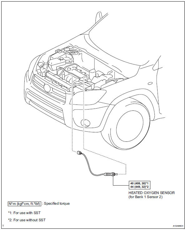
- Remove heated oxygen sensor (for bank 1 sensor 2)
- Disconnect the sensor connector.
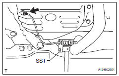
- Using sst, remove the sensor from the front exhaust pipe.
Sst 09224-00010
Inspection
- Inspect heated oxygen sensor (for bank 1 sensor 2)
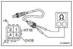
- Measure the resistance of the sensor.
Standard resistance 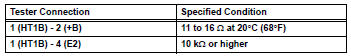
If the resistance is not as specified, replace the sensor.
Installation
- Install heated oxygen sensor (for bank 1 sensor 2)
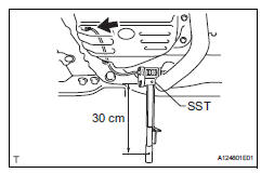
- Using sst, install the sensor to the front exhaust pipe.
Sst 09224-00010
Torque: 40 n*m (408 kgf*cm, 30 ft.*Lbf) for use with sst
44 N*m (449 kgf*cm, 32 ft.*Lbf) for use without sst
Hint:
- Use a torque wrench with a fulcrum length of 30 cm (11.81 In.).
- Make sure sst and wrench are connected in a straight line.
- Connect the sensor connector.
- Connect cable to negative battery terminal
- Check for exhaust gas leaks
 Air fuel ratio sensor
Components
On-vehicle inspection
Check air fuel ratio compensation system
Connect the intelligent tester to the dlc3.
Turn the ignition switch on.
Select the following menu item ...
 Fuel tank cap
Inspection
Inspect fuel tank cap assembly
Visually check that the cap and gasket are not
deformed or damaged.
If the result is not as specified, replace the cap
assembly or gaske ...
Other materials:
Automatic transaxle fluid
On-vehicle inspection
Check transaxle fluid level
Hint:
Drive the vehicle so that the engine and transaxle are at
normal operating temperature.
Fluid temperature:
70 to 80°c (158 to 176°f)
Park the vehicle on a level surface and set the
parking brake.
With the engine idling and ...
Switches
Driving position memory switches*1
Window lock switch
Power window switches
Door lock switches
Outside rear view mirror switches
"ODO TRIP" switch (vehicles with 7-inch multi-information display)
"ODO TRIP" switch (vehicles with 12.3-inch multi-information
display)
Instrument panel light ...
Dtc check / clear
Check dtc
Connect the intelligent tester (with can vim) to the
dlc3.
Turn the ignition switch on and turn the intelligent
tester on.
Read the dtc by following the prompts on the
tester screen.
Hint:
Refer to the intelligent tester operator's manual for
further details.
...
