Toyota RAV4 (XA40) 2013-2018 Service Manual: Front lower ball joint
Components
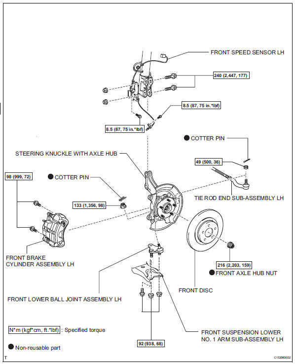
Removal
Hint:
- Use the same procedures for the rh side and lh side.
- The procedures listed below are for the lh side.
- Remove front wheel
- Remove front speed sensor lh (for 2wd) (see page bc-191)
- Remove front brake cylinder assembly lh (see page br-40)
- Remove front disc (see page br-42)
- Remove front axle hub nut (see page ah-6)
- Disconnect front suspension lower no. 1 Arm sub-assembly lh (see page ah-7)
- Disconnect tie rod end sub-assembly lh (see page ps-42)
- Remove steering knuckle with axle hub (see page ah-7)
- Remove front lower ball joint assembly lh
- Remove the cotter pin and nut.
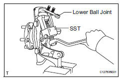
- Using sst, remove the lower ball joint.
Sst 09628-62011
Inspection
- Inspect front lower ball joint assembly lh
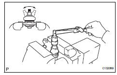
- As shown in the illustration, move the ball joint stud back and forth 5 times before installing the nut.
- Using a torque wrench, turn the nut continuously at a rate of 3 to 5 seconds per turn and take the torque reading on the fifth turn.
Standard turning torque: 0.98 To 3.43 N*m (10 to 35 kgf*cm, 9 to 30 in.*Lbf) or less
- Check for any cracks and grease leaks on the ball joint dust cover.
Installation
Hint:
- Use the same procedures for the rh side and lh side.
- The procedures listed below are for the lh side.
- Install front lower ball joint assembly lh
- Install the ball joint with the 2 bolts and nut to the lower arm.
Torque: 92 n*m (938 kgf*cm, 68 ft.*Lbf)
- Install the lower ball joint with the nut to the steering knuckle.
Torque: 133 n*m (1,360 kgf*cm, 98 ft.*Lbf)
- Install a new cotter pin.
If the holes for the cotter pin are not aligned, tighten the nut further up to 60°.
- Install steering knuckle with axle hub (see page ah-9)
- Connect front suspension lower no. 1 Arm sub-assembly lh (see page ah-10)
- Connect tie rod end sub-assembly lh (see page ps-45)
- Install front disc (see page br-43)
- Install front disc brake cylinder assembly lh (see page br-46)
- Install front axle hub nut (see page ah-10)
- Install front speed sensor lh (see page bc- 193)
- Install front wheel torque: 103 n*m (1,050 kgf*cm, 76 ft.*Lbf)
- Inspect and adjust front wheel alignment
- Inspect and adjust the front wheel alignment (see page sp-3).
 Front suspension lower no. 1 Arm
Components
Removal
Remove front wheel
Remove hood sub-assembly
Remove the hood (see page ed-4).
Suspend engine assembly
Install the no. 1 And no. 2 Engine hangers with the ...
 Front stabilizer bar
Components
Removal
Remove front wheel
Remove front stabilizer link assembly lh
Remove the 2 nuts and stabilizer link.
Remove front stabilizer link assembly rh
Hint:
Use ...
Other materials:
Installation (2006/01- )
Install abs and traction actuator assembly with bracket
Notice:
do not remove the hole plug before connecting the
brake tube. new actuators are filled with brake fluid.
Install the actuator with bracket with the 3 nuts.
Torque: 19 n*m (194 kgf*cm, 14 ft.*Lbf)
Hint:
The nuts should b ...
Rear view monitor
system
The rear view monitor system assists the driver by displaying an
image of the view behind the vehicle and fixation guide lines
while backing up, for example while parking.
The screen illustrations used in this text are intended as examples,
and may differ from the image that is actually displaye ...
Check for open circuit
For an open circuit in the wire harness in fig. 1,
Check the resistance or voltage, as described below.
Check the resistance.
Disconnect connectors a and c, and measure
the resistance between them.
Standard resistance (fig. 2)
Hint:
Measure the resistance while lightly s ...
