Toyota RAV4 (XA40) 2013-2018 Service Manual: Front stabilizer bar
Components
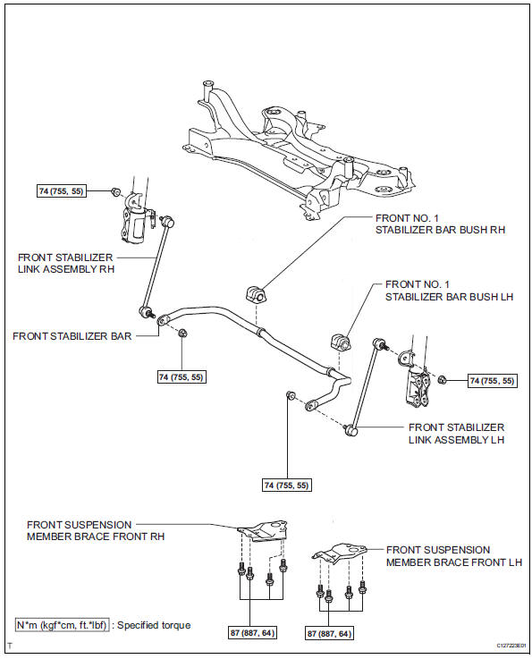
Removal
- Remove front wheel
- Remove front stabilizer link assembly lh
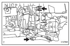
- Remove the 2 nuts and stabilizer link.
- Remove front stabilizer link assembly rh
Hint:
Use the same procedures described for the lh side.
- Remove front suspension member brace front lh
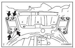
- Remove the 4 bolts and member brace from the corssmember.
- Remove front suspension member brace front rh
Hint:
Use the same procedures described for the lh side.
- Remove front stabilizer bar
- Remove the stabilizer bar from the crossmember.
- Remove front no. 1 Stabilizer bar bush lh
- Remove the bush from the stabilizer bar.
- Remove front no. 1 Stabilizer bar bush rh
Hint
Use the same procedures described for the lh side.
Inspection
- Inspect front stabilizer link assembly lh
- As shown in the illustration, move the ball joint stud back and forth 5 times before installing the nut.
- Using a torque wrench, turn the nut continuously at a rate of 3 to 5 seconds per turn and take the torque reading on the fifth turn.
Turning torque: 0.05 To 1.96 N*m, (0.5 To 20 kgf*cm, 0.4 To 17 in.*Lbf) or less
- Check for any cracks and grease leaks on the ball joint dust cover.
Installation
- Install front no. 1 Stabilizer bar bush lh
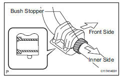
- Install the bush.
Hint:
- Install each bush to the inner side of each bush stopper on the stabilizer bar.
- Install each bush with its slit facing the vehicle rear side.
- Remove front no. 1 Stabilizer bar bush rh
Hint:
Use the same procedures described for the lh side.
- Install front stabilizer bar
- Install the stabilizer bar to the crossmember.
- Install front suspension member brace front lh
- Install the member brace with the 4 bolt to the suspension member.
Torque: 87 n*m (887 kgf*cm, 64 ft.*Lbf)
- Install front suspension member brace front rh
Hint:
Use the same procedures described for the lh side.
- Install front stabilizer link assembly lh
- Install the link with the 2 nut.
Torque: 74 n*m (755 kgf*cm, 55 ft.*Lbf)
- Install front stabilizer link assembly rh
Hint:
Use the same procedures described for the lh side.
- Install front wheel torque: 103 n*m (1,050 kgf*cm, 76 ft.*Lbf)
- Stabilize suspension (see page sp-12)
 Front lower ball joint
Components
Removal
Hint:
Use the same procedures for the rh side and lh side.
The procedures listed below are for the lh side.
Remove front wheel
Remove front speed sensor lh (for ...
 Rear coil spring
Components
Removal
Hint:
Use the same procedures for the rh side and lh side.
The procedures listed below are for the lh side.
Remove rear wheel
Remove skid control sensor wire (fo ...
Other materials:
Listening to bluetooth®
audio
The bluetooth® audio system enables the user to enjoy music
played on a portable player from the vehicle speakers via wireless
communication.
When a bluetooth® device cannot be connected, check the connection
status on the “bluetooth* audio” screen. If the device is not connected,
either ...
Crankshaft position sensor "A"
Description
The crankshaft position (ckp) sensor system consists of a ckp sensor plate
and a pickup coil.
The sensor plate has 34 teeth and is installed on the crankshaft. The pickup
coil is made of wound copper
wire, an iron core and magnet. The sensor plate rotates and, as each tooth ...
Multiplex communication circuit
Description
The air conditioning amplifier communicates data with the ecm and combination
meter through the can
communication system.
Wiring diagram
Inspection procedure
Check dtc
Clear the dtc (see page ac-31).
Read the dtc (see page ac-31).
Result
Go to can c ...
