Toyota RAV4 (XA40) 2013-2018 Service Manual: Rear coil spring
Components
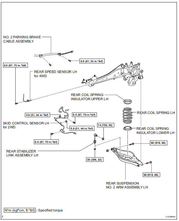
Removal
Hint:
- Use the same procedures for the rh side and lh side.
- The procedures listed below are for the lh side.
- Remove rear wheel
- Remove skid control sensor wire (for 2wd) (see page bc-198)
- Remove rear speed sensor lh (for 4wd) (see page bc-205)
- Disconnect no. 2 Parking brake cable assembly (see page pb-8)
- Disconnect rear stabilizer link assembly lh (see page sp-50)
- Disconnect rear suspension no. 2 Arm subassembly lh
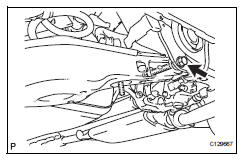
- Loosen the bolt from the suspension member side.
Notice:
Do not remove the bolt and nut. Only loosen them.
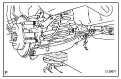
- Support the no. 2 Suspension arm lh with a jack.
Notice:
Place a wooden or rubber block between the jack and arm.
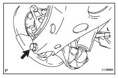
- Remove the bolt and nut from the axle carrier side.
- Slowly lower the jack, and disconnect the no. 2 Suspension arm from the axle carrier.
- Remove rear coil spring insulator upper lh
- Remove the insulator upper from the coil spring.
- Remove rear coil spring lh
- Remove the coil spring from the suspension no. 2 Arm
- Remove rear coil spring insulator lower lh
- Remove the insulator lower from the suspension no. 2 Arm.
Installation
Hint:
- Use the same procedures for the rh side and lh side.
- The procedures listed below are for the lh side.
- Install rear coil spring insulator lower lh
- Install the insulator lower to the suspension no. 2 Arm.
- Remove rear coil spring lh
- Install the coil spring to the suspension no. 2 Arm.
- Install rear coil spring insulator upper lh
- Align the stopper part of the insulator upper with the coil spring tip, and install the insulator upper.
- Temporarily install rear suspension no. 2 Arm assembly lh
- Slowly raise the suspension no. 2 Arm with a jack, and connect the suspension no. 2 Arm to the axle carrier.
- Install the bolt and nut.
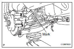
Notice:
Install the arm so that the coil spring's distinguishing mark is on the outer side of the vehicle.
- Install rear stabilizer link assembly lh (see page sp-50)
- Connect no. 2 Parking brake cable assembly (see page pb-9)
- Install skid control sensor wire (for 2wd) (see page bc-201)
- Install rear speed sensor lh (for 4wd) (see page bc-206)
- Install rear wheel torque: 103 n*m (1,050 kgf*cm, 76 ft.*Lbf)
- Stabilize suspension (see page sp-37)
- Tighten rear suspension no. 2 Arm assembly lh (see page sp-46)
- Check speed sensor signal
- Check the speed sensor signal (see page bc-44).
- Inspect and adjust rear wheel alignment
- Inspect and adjust the rear wheel alignment (see page sp-7).
 Front stabilizer bar
Components
Removal
Remove front wheel
Remove front stabilizer link assembly lh
Remove the 2 nuts and stabilizer link.
Remove front stabilizer link assembly rh
Hint:
Use ...
 Rear shock absorber
Components
Removal
Hint
Use the same procedures for the rh side and lh side.
The procedures listed below are for the lh side.
Remove rear wheel
Remove rear shock absorber assembly ...
Other materials:
Differential oil
On-vehicle inspection
Check differential oil
Stop the vehicle on a level surface.
Using a 10 mm socket hexagon wrench, remove the
rear differential filler plug and gasket.
Check that the oil level is between 0 to 5 mm (0 to
0.20 In.) From the bottom lip of the different ...
Removal and installation of engine intake parts
If any metal particles enter inlet system parts, they
may damage the engine.
When removing and installing inlet system parts,
cover the openings of the removed parts and engine
openings. Use gummed tape or other suitable
materials.
When installing inlet system parts, check that no ...
Installation
Notice:
Do not heat the vehicle body, emblem and name plate
excessively.
Hint:
When installing the emblem and name plate, heat the vehicle
body, emblem and name plate using a heat light.
Standard heating temperature
Install no. 4 Back door name plate (for 4wd)
Clean the vehicle body ...
