Toyota RAV4 (XA40) 2013-2018 Service Manual: Air fuel ratio sensor
Components
On-vehicle inspection
- Check air fuel ratio compensation system
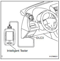
- Connect the intelligent tester to the dlc3.
- Turn the ignition switch on.
- Select the following menu items: data list / a/fs b1 s1 and o2s b1 s2.
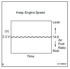
- Warm up the a/f sensor with the engine speed at 2,500 rpm for approximately 2 minutes.
- Keep the engine speed at 2,500 rpm and confirm that the display of "a/fs b1 s1" is as shown in the illustration.
Hint:
- The illustration may slightly differ from the display on the intelligent tester.
- Only the intelligent tester displays the waveform of the a/f sensor.
- Confirm that the display of "o2s b1 s2" changes between 0 to 1 v with the engine speed at 2,500 rpm.
Ok: the voltage output oscillates more than 8 times in 10 seconds.
Notice:
- Perform the check immediately after warming the engine up.
- If the voltage variation could not be verified, warm up the a/f sensor again. If it could not be verified even after warming up the sensor again, check for dtcs (see page es-292).
Removal
- Disconnect cable from negative battery terminal
Caution:
Wait at least 90 seconds after disconnecting the cable from the negative (-) battery terminal to prevent airbag and seat belt pretensioner activation.
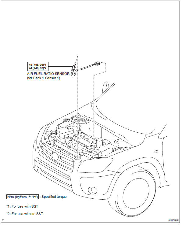
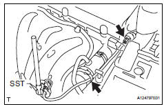
- Remove air fuel ratio sensor (for bank 1 sensor 1)
- Disconnect the sensor connector.
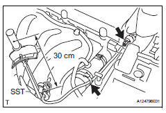
- Using sst, remove the sensor from the exhaust manifold.
Sst 09224-00010
Inspection
- Inspect air fuel ratio sensor (for bank 1 sensor 1)
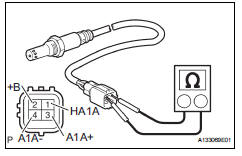
- Measure the resistance of the sensor.
Standard resistance 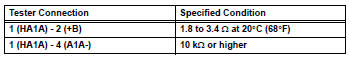
If the resistance is not as specified, replace the sensor.
Installation
- Install air fuel ratio sensor (for bank 1 sensor 1)
- Using sst, install the sensor to the exhaust manifold.
Sst 09224-00010
Torque: 40 n*m (408 kgf*cm, 30 ft.*Lbf) for use with sst
44 N*m (449 kgf*cm, 32 ft.*Lbf) for use without sst
Hint:
- Use a torque wrench with a fulcrum length of 30 cm (11.81 In.).
- Make sure sst and wrench are connected in a straight line.
- Connect the sensor connector.
- Connect cable to negative battery terminal
- Check for exhaust gas leaks
 Ventilation valve
Components
Removal
Remove no. 1 Engine cover (see page em-22)
Remove ventilation valve sub-assembly
Disconnect the ventilation hose from the ventilation
valve.
Using a ...
 Heated oxygen sensor
Components
Removal
Disconnect cable from negative battery
terminal
Caution:
Wait at least 90 seconds after disconnecting the
cable from the negative (-) battery terminal to
prevent ai ...
Other materials:
Components
...
Transponder chip malfunction
Description
This dtc is output when: 1) during key code registration, a key malfunction
occurs; 2) the key code was
unable to be registered properly.
Inspection procedure
Reregister key
Clear the dtc (see page ei-18).
Reregister the key code with the transponder key ecu
(s ...
Front fog light circuit
Description
The main body ecu controls the front fog light relay (marking: fr fog) when a
signal is received from
the headlight dimmer switch.
Wiring diagram
Inspection procedure
Perform active test by intelligent tester
Connect the intelligent tester (with can vim) to the
dlc3 ...
