Toyota RAV4 (XA40) 2013-2018 Service Manual: Reassembly
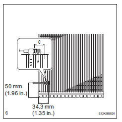
- Install evaporator temperature sensor
Notice:
If reusing the evaporator, do not insert the sensor to a location where the sensor was previously inserted.
Insert the sensor within range c shown in the illustration.
- Install the evaporator temperature sensor as shown in the illustration.
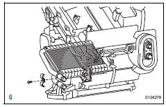
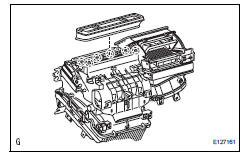
- Install no. 1 Cooler evaporator subassembly
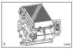
- Install the cooler thermistor and cooler evaporator on the case.
- Attach the temperature sensor clamp.
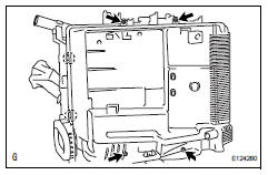
- Attach the 2 claws to install the cover.
- Install the 4 screws.
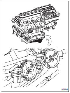
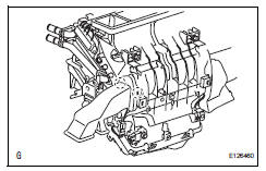
- Install cooler expansion valve
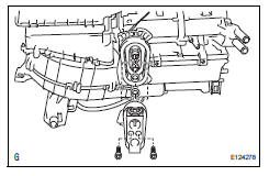
- Sufficiently apply compressor oil to 2 new o-rings and the fitting surface of the hose joint.
Compressor oil: nd-oil 8 or equivalent
- Install the 2 o-rings to the cooler evaporator.
- Install the cooler expansion valve.
- Using a 4 mm hexagon wrench, install the a/c tube with the 2 hexagon bolts.
Torque: 3.5 N*m (35 kgf*cm, 30 in.*Lbf)
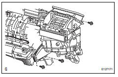
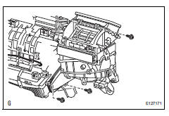
- Install heater radiator unit sub-assembly
- Install the heater radiator with the clamp and screw.
- Install airmix damper control cable subassembly (for manual air conditioning system)
- Attach the 3 claws to install the cable.
- Install mode control cable assembly (for manual air conditioning system)

- Attach the 3 claws to install the cable.
- Attach the evaporator case to the blower case.
- Install the cable with the 3 screws.
- Install air mix control servo motor
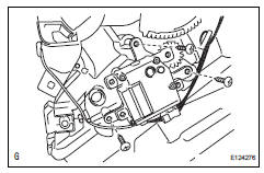
- Install the air mix control servo motor with the 3 screws and connect the connector.
- Install air outlet control servo motor
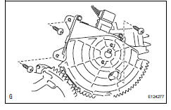
- Install the air outlet control servo motor with the 3 screws and connect the connector.
- Attach the evaporator case to the blower case.
- Install the 3 screws.
- Install air duct
- Attach the 2 claws and install the air duct.
- Install no. 3 Heater to register duct
- Attach the 6 claws and install the heater to register duct.
 Disassembly
Remove no. 3 Heater to register duct
Detach the 6 claws and remove the heater to
register duct.
Remove air duct
Detach the 2 claws and remove the air duct.
Remove ...
 Installation
Install air conditioner unit assembly
Install the a/c unit with the bolt and nut.
Torque: 9.8 N*m (100 kgf*cm, 7 ft.*Lbf)
Install instrument panel reinforcement
Install th ...
Other materials:
Ig power source circuit
Description
This is the main power source supplied to the air conditioning amplifier when
the ignition switch is on.
This power source is used for operating components, such as the air conditioning
amplifier and servo
motors.
Wiring diagram
Inspection procedure
Inspect fuse (ecu-i ...
How to proceed with troubleshooting
Hint:
Use the following procedures to troubleshoot the occupant
classification system.
*: Use the intelligent tester.
Vehicle brought to workshop
Passenger airbag on/off indicator check
Dtc check (present and past dtc)*
Check for dtcs (see page rs-249 ).
Result ...
Back-up light circuit
Description
The park / neutral position switch turns on when the shift lever is moved
into the r position, causing the
back-up lights to illuminate.
Wiring diagram
Inspection procedure
Inspect fuse (gauge1)
Remove the gauge1 fuse from the instrument panel
junction block.
Meas ...
