Toyota RAV4 (XA40) 2013-2018 Service Manual: Lost communication with front satellite sensor bus rh
Description
The front airbag sensor rh consists of the diagnostic circuit and the frontal deceleration sensor.
If the center airbag sensor receives signals from the frontal deceleration sensor, it determines whether or not the srs should be activated.
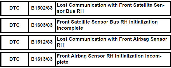
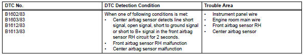
Dtc b1602/83, b1603/83, b1612/83 or b1613/83 is recorded when a malfunction is detected in the front airbag sensor rh circuit.
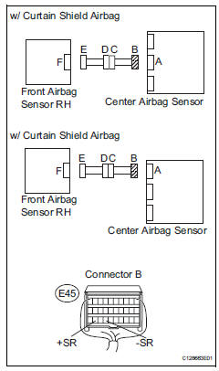
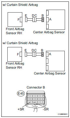
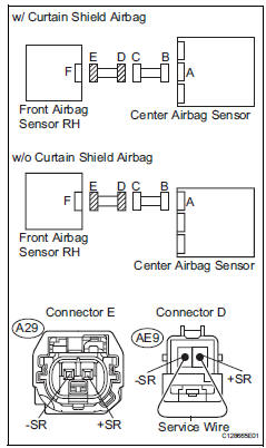
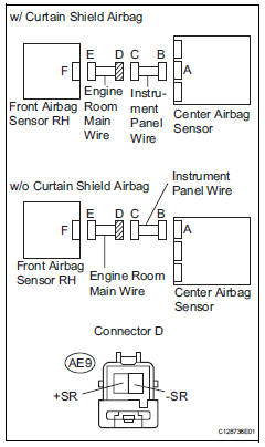
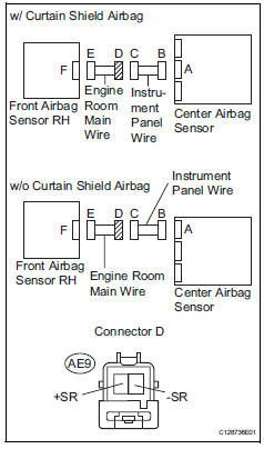
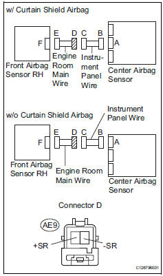
Wiring diagram
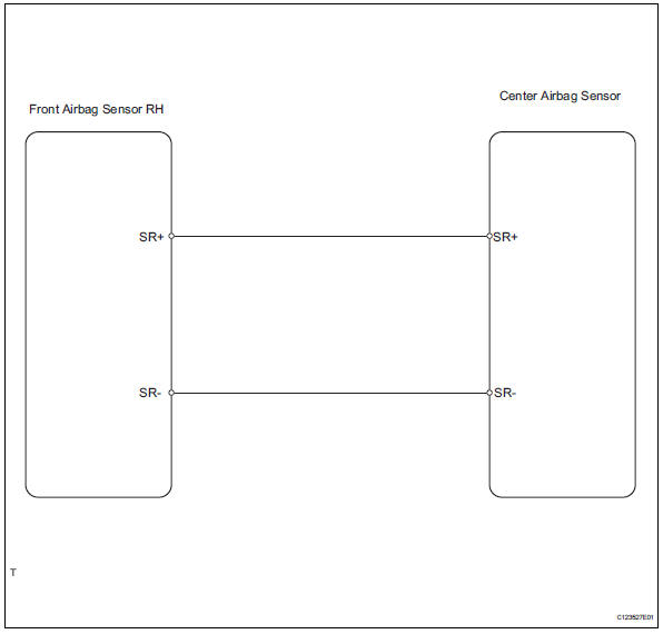
Inspection procedure
- Check connection of connector
- Turn the ignition switch off.
- Disconnect the cable from the negative (-) battery terminal, and wait for at least 90 seconds.
- Check that the connectors are properly connected to the center airbag sensor and the front airbag sensor rh.
Ok: the connectors are connected.

- Check front airbag sensor rh circuit (open)
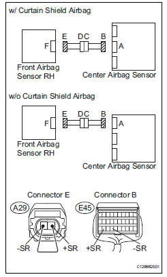
- Disconnect the connectors from the center airbag sensor and the front airbag sensor rh.
- Using a service wire, connect a29-2 (+sr) and a29-1 (- sr) of connector e.
Notice:
Do not forcibly insert a service wire into the terminals of the connector when connecting.
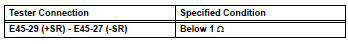
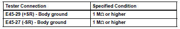
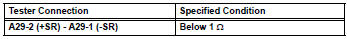
- Measure the resistance of the wire harness side connector.
Standard resistance

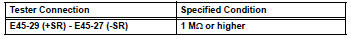
- Check front airbag sensor rh circuit (short)
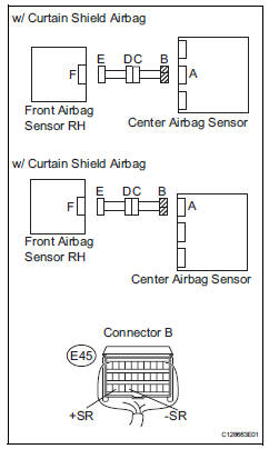
- Disconnect the service wire from connector e.
- Measure the resistance of the wire harness side connector.
Standard resistance

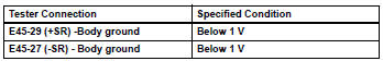
- Check front airbag sensor rh circuit (to b+)
- Connect the cable to the negative (-) battery terminal, and wait for at least 2 seconds.
- Turn the ignition switch on.
- Measure the voltage of the wire harness side connector.
Standard voltage

- Check front airbag sensor rh circuit (to ground)
- Turn the ignition switch off.
- Disconnect the cable from the negative (-) battery terminal, and wait for at least 90 seconds.
- Measure the resistance of the wire harness side connector.
Standard resistance


- Check front airbag sensor rh
- Connect the connectors to the center airbag sensor .
- Interchange the front airbag sensor rh and lh, and connect the connectors to them.
- Connect the cable to the negative (-) battery terminal, and wait for at least 2 seconds.
- Turn the ignition switch on, and wait for at least 60 seconds.
- Clear the dtcs (see page rs-49).
- Turn the ignition switch off.
- Turn the ignition switch on, and wait for at least 60 seconds.
- Check the dtcs (see page rs-49).
Result 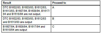
Hint:
Dtcs other than dtc b1602/83, b1603/83, b1612/83, b1613/83, b1607/84, b1608/84, b1617/84 and b1618/ 84 may be output at this time, but they are not related to this check.

Use simulation method to check
- Check engine room main wire (open)
- Disconnect the service wire from connector e.
- Disconnect the engine room main wire connector from the instrument panel wire.
- Using a service wire, connect ae9-2 (+sr) and ae9-1 (- sr) of connector d.
Notice:
Do not forcibly insert a service wire into the terminals of the connector when connecting.
- Measure the resistance of the wire harness side connector.
Standard resistance

Repair or replace instrument panel wire
- Check engine room main wire (short)
- Disconnect the engine room main wire connector from the instrument panel wire.
- Disconnect the service wire from connector e.
- Measure the resistance of the wire harness side connector.
Standard resistance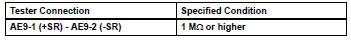

Repair or replace instrument panel wire
- Check engine room main wire (to b+)
- Turn the ignition switch off.
- Disconnect the cable from the negative (-) battery terminal, and wait for at least 90 seconds.
- Disconnect the engine room main wire connector from the instrument panel wire.
- Connect the cable to the negative (-) battery terminal, and wait for at least 2 seconds.
- Turn the ignition switch on.
- Measure the voltage of the wire harness side connector.
Standard voltage

Repair or replace instrument panel wire
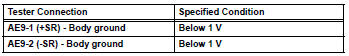
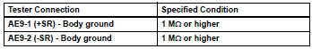
- Check engine room main wire (to ground)
- Disconnect the engine room main wire connector from the instrument panel wire.
- Measure the resistance of the wire harness side connector.
Standard resistance

Repair or replace instrument panel wire
 Center airbag sensor assembly malfunction
Description
The center airbag sensor consists of the airbag sensor, the safing sensor,
the drive circuit, the diagnosis
circuit and the ignition control.
If the center airbag sensor receive ...
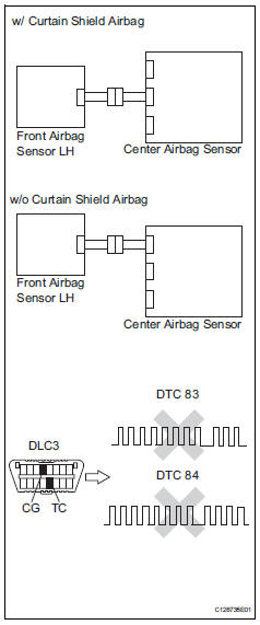
 Lost communication with front satellite sensor bus lh
Description
The front airbag sensor lh consists of the diagnostic circuit and the frontal
deceleration sensor.
If the center airbag sensor receives signals from the frontal deceleration
se ...
Other materials:
Brake switch "B" circuit high
Description
The purpose of this circuit is to prevent the engine from stalling while
driving in the lock-up condition when
the brakes are suddenly applied.
When the brake pedal is depressed, this switch sends a signal to the ecm. Then
the ecm cancels the
operation of the lock-up clutch ...
If you think something is
wrong
If you notice any of the following
symptoms, your
vehicle probably needs
adjustment or repair. Contact
your Toyota dealer as
soon as possible.
Visible symptoms
Fluid leaks under the vehicle
(Water dripping from the air
conditioning after use is normal.)
Flat-looking tires or uneven
tire wear
...
Fuel consumption information
The fuel consumption information
can be displayed on
the Multimedia Display.
Display procedure
Press on the main menu,
then press "Trip information" on
the sub menu.
For detail regarding the Multimedia
Display, refer to "MULTIMEDIA
OWNER'S MANUAL".
â– Current fuel consumption
screen
If a screen o ...
