Toyota RAV4 (XA40) 2013-2018 Service Manual: Lost communication with front satellite sensor bus lh
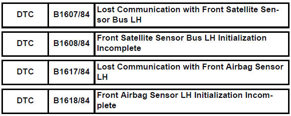
Description
The front airbag sensor lh consists of the diagnostic circuit and the frontal deceleration sensor.
If the center airbag sensor receives signals from the frontal deceleration sensor, it determines whether or not the srs should be activated.
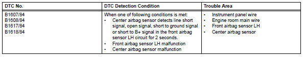
Dtc b1607/84, b1608/84, b1617/84 or b1618/84 is recorded when a malfunction is detected in the front airbag sensor lh circuit.
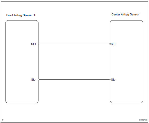
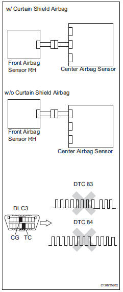
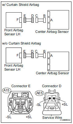
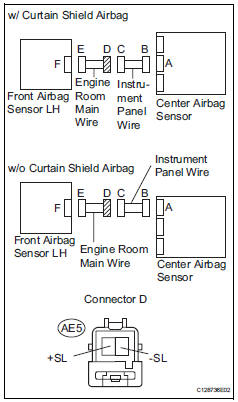
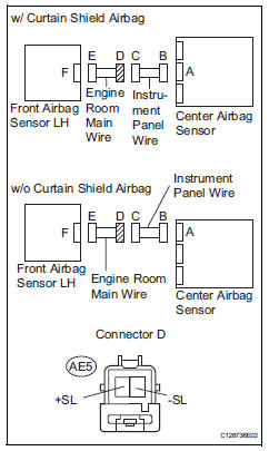
Wiring diagram
Inspection procedure
- Check connection of connector
- Turn the ignition switch off.
- Disconnect the cable from the negative (-) terminal, and wait for at least 90 seconds.
- Check that the connectors are properly connected to the center airbag sensor and the front airbag sensor lh.
Ok: the connectors are properly connected.

- Check front airbag sensor lh circuit (open)
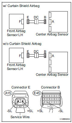
- Disconnect the connectors from the center airbag sensor and the front airbag sensor lh.
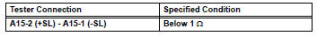
- Using a service wire, connect a15-2 (+sl) and a15-1 (- sl) of connector e.
Notice:
Do not forcibly insert a service wire into the terminals of the connector when connecting.
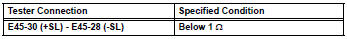
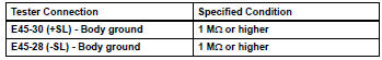
- Measure the resistance of the wire harness side connector.
Standard resistance


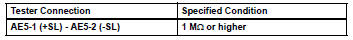
- Check front airbag sensor lh circuit (short)
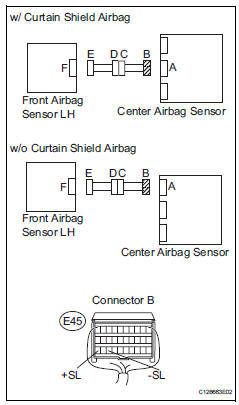
- Disconnect the service wire from connector e.
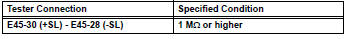
- Measure the resistance of the wire harness side connector.
Standard resistance

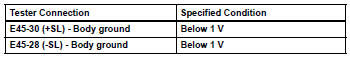
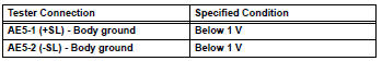
- Check front airbag sensor lh circuit (to b+)
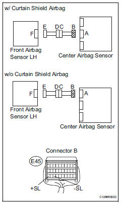
- Connect the cable to the negative (-) battery terminal, and wait for at least 2 seconds.
- Turn the ignition switch on.
- Measure the voltage of the wire harness side connectors.
Standard voltage


- Check front airbag sensor lh circuit (to ground)
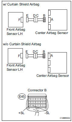
- Turn the ignition switch off.
- Disconnect the cable from the negative (-) battery terminal, and wait for at least 90 seconds.
- Measure the resistance of the wire harness side connector.
Standard resistance


- Check front airbag sensor lh
- Connect the connectors to the center airbag sensor.
- Interchange the front airbag sensor rh and lh, and connect the connectors to them.
- Connect the cable to the negative (-) battery terminal, and wait for at least 2 seconds.
- Turn the ignition switch on, and wait for at least 60 seconds.
- Clear the dtcs (see page rs-49).
- Turn the ignition switch off
- Turn the ignition switch on, and wait for at least 60 seconds.
- Check the dtcs (see page rs-49).
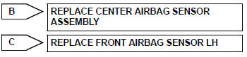
Result 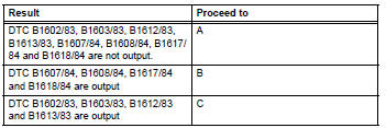
Hint:
Dtcs other than b1602/83, b1603/83, b1612/83, b1613/83, b1607/84, b1608/84, b1617/84 and b1618/ 84 may be output at this time, but they are not related to this check.

Use simulation method to check
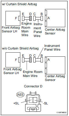
- Check engine room main wire (open)
- Disconnect the service wire from connector e.
- Disconnect the engine room main wire connector from the instrument panel wire.
- Using a service wire, connect ae5-1 (+sl) and ae5-2 (- sl) of connector d.
Notice:
Do not forcibly insert a service wire into the terminals of the connector when connecting.
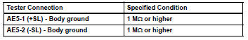
- Measure the resistance of the wire harness side connector.
Standard resistance

Repair or replace instrument panel wire
- Check engine room main wire (short)
- Disconnect the engine room main wire connector from the instrument panel wire.
- Measure the resistance of the wire harness side connector.
Standard resistance

Repair or replace instrument panel wire
- Check engine room main wire (to b+)
- Turn the ignition switch off.
- Disconnect the cable from the negative (-) battery terminal, and wait for at least 90 seconds.
- Disconnect the engine room main wire connector from the instrument panel wire.
- Connect the cable to the negative (-) battery terminal, and wait for at least 2 seconds.
- Turn the ignition switch on.
- Measure the voltage of the wire harness side connector
Standard voltage

Repair or replace instrument panel wire
- Check engine room main wire (to ground)
- Disconnect the engine room main wire connector from the instrument panel wire.
- Measure the resistance of the wire harness side connector.
Standard resistance

Repair or replace instrument panel wire
 Lost communication with front satellite sensor bus rh
Description
The front airbag sensor rh consists of the diagnostic circuit and the frontal
deceleration sensor.
If the center airbag sensor receives signals from the frontal deceleration
se ...
 Front airbag sensor rh circuit malfunction
Description
The front airbag sensor rh consists of the diagnostic circuit, the frontal
deceleration sensor, etc.
If the center airbag sensor assembly receives signals from the frontal
dece ...
Other materials:
Luggage compartment features
Cargo hooks
Raise the hook to use.
The cargo hooks are provided for
securing loose items.
WARNING
â– When cargo hooks are not in
use
To avoid injury, always return the
hooks to their stowed positions
when not in use.
Deck board
â– Flipping the deck board
upside down
The deck board can be flipped
...
Rear drive shaft assembly
Components
Removal
Hint:
Use the same procedures for the rh side and lh side.
The procedures listed below are for the lh side.
Disconnect cable from negative battery
terminal
Caution:
Wait at least 90 seconds after disconnecting the
cable from the negative (-) battery termin ...
Diagnostic trouble code chart
Look for output diagnostic trouble codes (dtcs) (from the
dtc checks) in the appropriate section's diagnostic trouble
code chart. Use the chart to determine the trouble area and
the proper inspection procedure. A description of each of the
chart's columns are below.
Item
Description
...
