Toyota RAV4 (XA40) 2013-2018 Service Manual: Open in abs solenoid relay circuit
Description
The solenoid relay supplies power to the abs solenoid and trc solenoid.
After the ignition switch is turned on, the vehicle speed has reached 6 km/h (4 mph) and the solenoid is determined to be normal by the initial check self-diagnosis, the relay switches on. If any open or short circuits are detected, the relay switches off.
These dtcs may be set if the voltage supply to the solenoid relay (+bs) falls below the dtc detection threshold due to the battery or alternator outputs being insufficient.
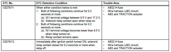
Hint:
Dtcs c0278/11 and c0279/12: the skid control ecu begins to detect these dtcs when the vehicle speed exceeds 6 km/h (4 mph).
Wiring diagram
Refer to dtc c0273/13, c0274/14, c1361/91 (see page bc-79).
Inspection procedure
- Inspect fuses (abs2)
- Remove the abs2 h-fuse from the engine room no. 1 Relay block.
- Measure the resistance of the fuse.
Standard resistance:
below 1 

- Check wire harness (skid control ecu - battery and body ground)
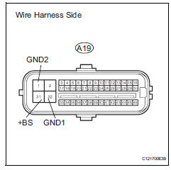
- Disconnect the a19 ecu connector.
- Measure the voltage of the wire harness side connector.
Standard voltage 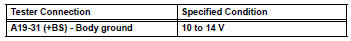
- Measure the resistance of the wire harness side connector.
Standard resistance 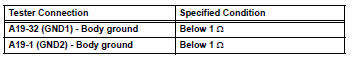

- Reconfirm dtc
- Clear the dtcs (see page bc-47).
- Start the engine.
- Drive the vehicle at 6 km/h (4 mph) or more to activate the initial check.
- Check if the same dtcs is output (see page bc-47).
Result 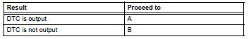

Replace abs and traction actuator assembly
 Solenoid circuit
Description
This solenoid is turned on in accordance with signals from the skid control
ecu and controls the pressure
on the wheel cylinders to control the braking force.
The solenoid and s ...
 Engine control system malfunction
Description
If a malfunction in the engine control system is detected, the operations of
vsc and trc are prohibited
by the fail-safe function. When the signals from the engine are input normal ...
Other materials:
List of storage features
Location of the storage features
Open tray
Auxiliary boxes
Bottle holders
Console box
Cup holders
Glove box
WARNING
â– Items that should not be left
in the vehicle
Do not leave glasses, lighters or
spray cans in the storage spaces,
as this may cause the following
when cabin temperature beco ...
Side airbag sensor
Components
On-vehicle inspection
Check side airbag sensor (vehicle not
involved in collision)
Perform a diagnostic system check (see page rs-
49).
Check side airbag sensor (vehicle involved
in collision and airbag has not deployed)
Perform a diagnostic system check ( ...
Steering angle sensor communication stop mode
Description
Wiring diagram
Inspection procedure
Notice:
Turn the ignition switch off before measuring the resistances of the
main wire and the branch
wire.
After the ignition switch is turned off, check that the key reminder
warning system and light
reminder warning system ...
