Toyota RAV4 (XA40) 2013-2018 Service Manual: Reassembly
- Install generator rotor assembly
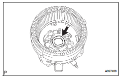
- Install the washer onto the generator rectifier end frame.
- Install the generator rotor onto the generator rectifier end frame.
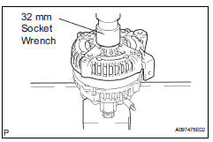
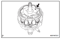
- Using a 32 mm socket wrench and press, slowly push the generator drive end frame onto the generator rectifier end frame.
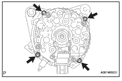
- Tighten the 4 bolts.
Torque: 5.8 N*m (59 kgf*cm, 51 in.*Lbf)
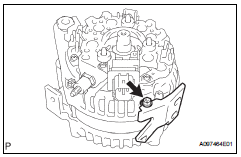
- Install the cord clip with the bolt.
Torque: 4.6 N*m (47 kgf*cm, 41 in.*Lbf)
- Install generator brush holder assembly
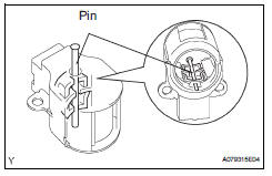
- While pushing the 2 brushes into the generator brush holder, insert a 1.0 Mm (0.039 In.) Pin into the generator brush holder.
- Install the generator brush holder with the 2 screws.
Torque: 1.8 N*m (18 kgf*cm, 16 in.*Lbf)
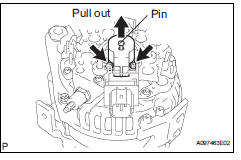
- Pull the pin out of the generator brush holder.
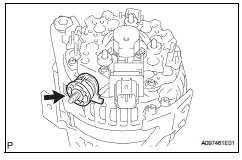
- Install the terminal insulator onto the generator rectifier end frame.
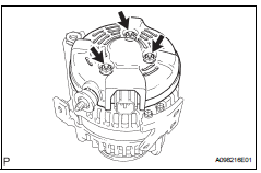
- Install the generator rear end cover with the 3 nuts.
Torque: 4.6 N*m (47 kgf*cm, 41 in.*Lbf)
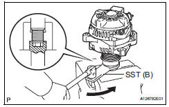
Install generator pulley with clutch
- Install the pulley by hand.
- Install sst to the pulley and vise as shown in the illustration.
Sst 09820-63020
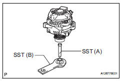
- Turn sst (b) counterclockwise to tighten the pulley.
Torque: 111 n*m (1125 kgf*cm, 81 ft.*Lbf)
- Install a new cap to the pulley.
- Check that the generator pulley rotates smoothly.
 Replacement
Replace generator drive end frame bearing
Remove the 4 screws and bearing retainer.
Using sst and a hammer, tap out the bearing.
Sst 09950-60010 (09951-00250), 09950-70010
(0995 ...
 Installation
Install generator assembly
Confirm that the wire harness of the crankshaft
position sensor is secured to the wire harness
clamp bracket through the back of the rib of the
timing cha ...
Other materials:
Removal
Discharge fuel system pressure (see page
fu-9)
Disconnect cable from negative battery
terminal
Caution:
Wait at least 90 seconds after disconnecting the
cable from the negative (-) battery terminal to
prevent airbag and seat belt pretensioner activation.
Remove radiator support op ...
Parking Support Brake function
(static objects)
If the sensors detect a static object, such as a wall, in the
traveling direction of the vehicle and the system determines
that a collision may occur due to the vehicle suddenly moving
forward due to an accidental accelerator pedal operation, the
vehicle moving the unintended direction due to the wr ...
Reassembly
Install sliding roof drive cable
Using a screwdriver, slide the sliding roof drive
cable sub-assemblies in the direction indicated by
the arrow in the illustration to install them.
Hint:
Tape the screwdriver tip before use.
Engage the 2 claws and install the sliding roof ...
