Toyota RAV4 (XA40) 2013-2018 Service Manual: Installation
- Install generator assembly
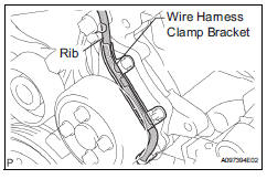
- Confirm that the wire harness of the crankshaft position sensor is secured to the wire harness clamp bracket through the back of the rib of the timing chain cover.
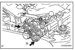
- Install the generator with the 2 bolts.
Torque: 21 n*m (215 kgf*cm, 16 ft.*Lbf) for bolt a 52 n*m (530 kgf*cm, 38 ft.*Lbf) for bolt b
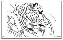
- Install the wire harness clamp.
- Install the wire harness clamp bracket with the bolt.
Torque: 8.4 N*m (85 kgf*cm, 74 in.*Lbf)
- Connect the generator wire with the nut.
Torque: 9.8 N*m (100 kgf*cm, 7 ft.*Lbf)
- Install the terminal cap.
- Connect the generator connector.
- Install fan and generator v belt
- Install the belt (see page em-7).
- Connect cable to negative battery terminal
 Reassembly
Install generator rotor assembly
Install the washer onto the generator rectifier end
frame.
Install the generator rotor onto the generator
rectifier end frame.
Usi ...
 Battery current sensor
On-vehicle inspection
Check battery current sensor assembly
Measure the resistance of the sensor.
Standard resistance
If the result is not as specified, replace the sensor
assembly.
...
Other materials:
Problem symptoms table
Hint:
Use the table below to help determine the cause of the
problem symptom. The potential causes of the symptoms are
listed in order of probability in the "suspected area" column
of the table. Check each symptom by checking the suspected
areas in the order they are listed. Replace p ...
Catalyst monitor (active air-fuel ratio control type)
Preconditions
The monitor will not run unless:
The mil is off.
Drive pattern
Connect the intelligent tester to the dlc3.
Turn the ignition switch on.
Turn the tester on.
Clear dtcs (if set) (see page es-35).
Start the engine and warm it up.
Drive the vehicle at be ...
Fail-safe chart
If a problem occurs in the electric power steering system, the
p/s warning light will come on in the combination meter and
steering power assist will be stopped, fixed at a particular
point, or decreased simultaneously to protect the system.
Hint:
The amount of power assist may be decreased ...
