Toyota RAV4 (XA40) 2013-2018 Service Manual: Removal
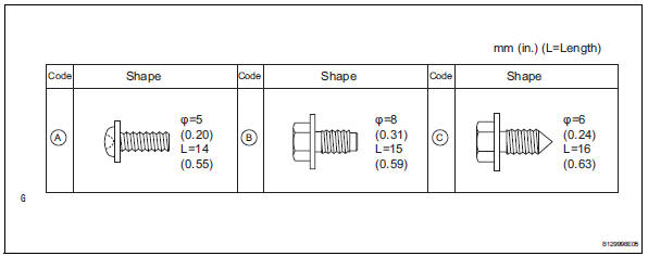
- Table of bolt, screw and nut
Hint:
All bolts, screws and nuts relevant to installing and removing the instrument panel are shown along with their alphabet codes in the table below.
- Disconnect cable from negative battery terminal
Caution:
Wait at least 90 seconds after disconnecting the cable from the negative (-) battery terminal to prevent airbag and seat belt pretensioner activation.
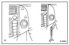
- Remove instrument cluster finish panel sub-assembly
- Using a screwdriver, detach the 4 clips, 6 claws and remove the instrument cluster finish panel.
Hint:
Tape the screwdriver tip before use.
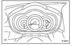
- Remove combination meter assembly
- Remove the 2 screws.
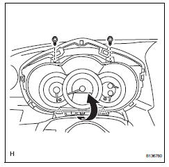
- Pull the combination meter as indicated by the arrow in the illustration to detach the 2 clips.
- Disconnect the connector and remove the combination meter.
- Remove no. 2 Instrument cluster finish panel center
- Using a screwdriver, detach the 3 clips, 3claws and remove the cluster finish panel, then disconnect the connector.
Hint:
Tape the screwdriver tip before use.
- Remove no. 1 Instrument cluster finish panel center
- Using a screwdriver, detach the 3 clips, 3claws and remove the cluster finish panel, then disconnect the connector.
Hint:
Tape the screwdriver tip before use.
- Remove radio receiver
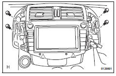
- Remove the 4 bolts.
- Detach the 4 clips, remove the radio receiver and then disconnect the connectors.
- Remove instrument panel register assembly center
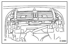
- Using a screwdriver, detach the 5 clips and remove the instrument panel register.
Hint:
Tape the screwdriver tip before use.
- Remove glove compartment door assembly (see page ip-20)
- Remove front pillar garnish lh (see page ir- 27)
- Remove front pillar garnish rh (see page ir- 28)
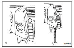
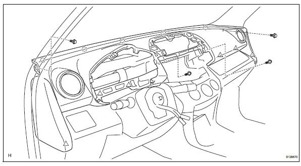
- Remove upper instrument panel
- Remove the 2 bolts from the passenger airbag.
- Disconnect the passenger airbag connector.
- Remove the 2 bolts and 2 screws.
- Disconnect the connectors and clamps.
- Detach the 6 clips and 5 claws and remove the instrument panel.
 Precaution
Precaution for vehicle with srs airbag and
seat belt pretensioner
Some operations in this section may affect the srs
airbags and seat belt pretensioner. Prior to
performing the corresp ...
 Disassembly
Remove no. 1 Side defroster nozzle duct
Remove the 3 screws and duct.
Remove no. 2 Side defroster nozzle duct
Remove the 3 screws and duct.
Remove no. 1 Heater to re ...
Other materials:
Camshaft position "A"
Dtc P0011 Camshaft position
"a" - timing over-advanced or system performance (bank 1)
Dtc P0012 Camshaft
position "a" - timing over-retarded (bank 1)
Description
The vvt system includes the ecm, oil control valve (ocv) and vvt controller.
The ecm sends a target
du ...
Check for intermittent problems
Hint:
Inspect the vehicle's ecm using check mode. Intermittent
problems are easier to detect with the intelligent tester when
the ecm is in check mode. In check mode, the ecm uses 1
trip detection logic, which is more sensitive to malfunctions
than normal mode (default), which uses 2 trip detec ...
Front seatback heater
Inspection
Inspect front seatback heater assembly
lh
Measure the resistance of the seatback heater.
Standard resistance
If the result is not as specified, replace the seatback
heater assembly
Inspect front seatback heater assembly
rh
Hint:
Use the same procedures desc ...
