Toyota RAV4 (XA40) 2013-2018 Service Manual: Removal (2005/11-2006/01)
- Remove front wheel
- Drain automatic transaxle fluid
- Drain the automatic transaxle fluid for u140f (see page ax-147).
- Drain the automatic transaxle fluid for u241e (see page ax-146).
- Remove front axle hub nut (see page ah-6)
- Disconnect front speed sensor lh (see page bc-191)
- Disconnect front speed sensor rh
Hint:
Use the same procedures described for the lh side.
- Disconnect front disc brake cylinder assembly lh (see page br-40)
- Disconnect front disc brake cylinder assembly rh
Hint:
Use the same procedures described for the lh side.
- Disconnect front stabilizer link assembly lh (see page sp-9)
- Disconnect front stabilizer link assembly rh
Hint:
Use the same procedures described for the lh side.
- Disconnect front suspension lower no. 1 Arm sub-assembly lh (see page ah-7)
- Disconnect front suspension lower no. 1 Arm sub-assembly rh
Hint:
Use the same procedures described for the lh side.
- Disconnect steering knuckle with axle hub lh
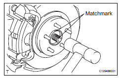
- Put matchmarks on the drive shaft and axle hub.
Notice:
Do not punch the marks.
- Using a plastic-faced hammer, disconnect the steering knuckle with axle hub.
Notice:
Be careful not to damage the boot and speed sensor rotor.
Do not excessively push out the drive shaft from the axle assembly.
- Disconnect steering knuckle with axle hub rh
Hint:
Use the same procedures described for the lh side.
- Disconnect steering knuckle with axle hub rh
Hint:
Use the same procedures described for the lh side.
- Disconnect tie rod end sub-assembly lh (see page ps-42)
- Disconnect tie rod end sub-assembly rh
Hint:
Use the same procedures described for the lh side.
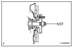
- Remove front drive shaft assembly lh
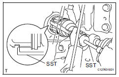
- Using sst, remove the front drive shaft.
Sst 09520-01010, 09520-24010 (09520-32040)
Notice:
- Be careful not to damage the transaxle case oil seal, inboard joint boot and drive shaft dust cover.
- Be careful not to drop the drive shaft.
- Remove front drive shaft assembly rh
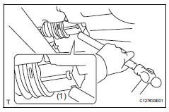
- Using a brass bar and hammer, set the brass bar against position (1) as shown in the illustration and remove the drive shaft.
Notice:
- Do not damage the oil seal.
- Do not damage the drive shaft boot.
- Do not allow the drive shaft to fall off.
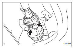
- Squeeze the ends of the snap ring, and remove the snap ring from the bearing bracket.
- Remove the bearing bracket bolt and remove the front drive shaft from the bearing bracket.
Notice:
- Do not damage the oil seal.
- Do not damage the boot.
- Do not allow the drive shaft to fall off.
Hint:
If the connection is stiff, use a brass bar and hammer to lightly tap the edge of the inboard joint rh and remove it.
- Fix front axle assembly
Notice:
The hub bearing could be damaged if it is subjected to the vehicle weight, such as when moving the vehicle with the drive shaft removed. Therefore, if it is absolutely necessary to place the vehicle weight on the hub bearing, first support it with sst.
Sst 09608-16042 (09608-02021, 09608-02041)
 Front drive shaft assembly (for 4wd)
Components (2005/11-2006/01)
Components (2006/01- )
...
 Removal
(2006/01- )
Removal
(2006/01- )
Remove front wheel
Drain automatic transaxle fluid
Drain the automatic transaxle fluid for u140f (see
page ax-147).
Drain the automatic transaxle fluid for u241e (see
page ax-146).
...
Other materials:
Trailer towing
Your vehicle is designed
primarily as a passenger-and-
load-carrying vehicle.
Towing a trailer can have an
adverse impact on handling,
performance, braking, durability,
and fuel consumption.
For your safety and the
safety of others, you must
not overload your vehicle or
trailer. You must also
ensu ...
Check mode procedure
Description
Check mode has a higher sensitivity to malfunctions
and can detect malfunctions that normal mode
cannot detect. Check mode can also detect all the
malfunctions that normal mode can detect. In check
mode, dtcs are detected with 1 trip detection logic.
Check mode pro ...
Removal
(2006/01- )
Remove front wheel
Drain automatic transaxle fluid
Drain the automatic transaxle fluid for u140f (see
page ax-147).
Drain the automatic transaxle fluid for u241e (see
page ax-146).
Drain the automatic transaxle fluid for u151f (see
page ax-173).
Remove front axle hub nut ( ...
