Toyota RAV4 (XA40) 2013-2018 Service Manual: Replacement
- discharge refrigerant from refrigeration system
- Start up the engine.
- Turn the a/c switch on.
- Operate the cooler compressor with an engine speed of approximately 1,000 rpm for 5 to 6 minutes to circulate the refrigerant and collect the compressor oil remaining in each component into the cooler compressor.
- Stop the engine.
- Using sst, discharge the refrigerant gas.
Sst 07110-58060 (07117-58060, 07117-58070, 07117-58080, 07117-58090, 07117-78050, 07117-88060, 07117-88070, 07117-88080)
- Charge refrigerant
- Perform vacuum purging using a vacuum pump.
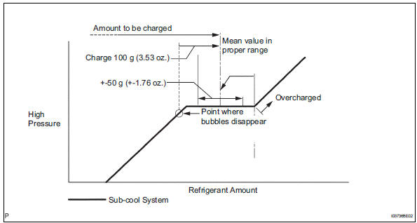
- Charge refrigerant hfc-134a (r134a).
Standard: 430 +-30 g (15.2 +-1.1 Oz.)
Sst 07110-58060 (07117-58060, 07117-58070, 07117-58080, 07117-58090, 07117-78050, 07117-88060, 07117-88070, 07117-88080)
Notice:
- Do not operate the cooler compressor before charging refrigerant as the cooler compressor will not work properly without any refrigerant, and will overheat.
- Approximately 100 g (3.53 Oz.) Of refrigerant may need to be charged after bubbles disappear. The refrigerant amount should be checked by measuring its quantity, and not with the sight glass.
- Warm up engine
- Warm up the engine at less than 1,850 rpm for 2 minutes or more after charging the refrigerant.
Notice:
Be sure to warm up the compressor when turning the a/c switch on after removing and installing the cooler refrigerant lines (including the compressor), to prevent damage to the compressor.
- Check for leakage of refrigerant
- After recharging the refrigerant gas, check for refrigerant gas leakage using a halogen leak detector.
- Perform the operation under these conditions:
- Stop the engine.
- secure good ventilation (the gas leak detector may react to volatile gases other than refrigerant, such as evaporated gasoline or exhaust gas).
- Repeat the test 2 or 3 times.
- Make sure that some refrigerant remains in the refrigeration system. When compressor is off: approximately 392 to 588 kpa (4 to 6 kgf/cm2, 57 to 85 psi)
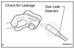
- Using a gas leak detector, check the refrigerant line for leakage.
- If a gas leak is not detected on the drain hose, remove the blower motor control (blower resistor) from the cooling unit. Insert the gas leak detector sensor into the unit and perform the test.
- Disconnect the connector and leave the pressure switch on for approximately 20 minutes. Bring the gas leak detector close to the pressure switch and perform the test.
 On-vehicle inspection
Inspect refrigerant pressure with
manifold gauge set
This method uses a manifold gauge set to locate
problem areas. Read the manifold gauge pressure
when these conditions are establishe ...
 Refrigerant line
Components (2005/11-2006/01)
Components (2006/01- )
...
Other materials:
Catalyst monitor (active air-fuel ratio control type)
Preconditions
The monitor will not run unless:
The mil is off.
Drive pattern
Connect the intelligent tester to the dlc3.
Turn the ignition switch on.
Turn the tester on.
Clear dtcs (if set) (see page es-35).
Start the engine and warm it up.
Drive the vehicle at be ...
Gauges and meters (with 7- inch multi-information
display)
The meters display various drive information.
Meter display
The display of the speedometer can be selected from two types,
analog or digital.
Analog speedometer
The units used on the meter and display may differ depending on the target
region.
Tachometer
Displays the engine speed in revolutions ...
Front axle hub
Components (2005/11-2006/01)
Components (2006/01- )
On-vehicle inspection
Check front axle hub bearing
Remove the front wheel.
Disconnect the front disc brake cylinder (see page
br-40).
Remove the front disc.
Inspect the axle hub backlash.
Using a dial indicator ...
