Toyota RAV4 (XA40) 2013-2018 Service Manual: Shift lock system
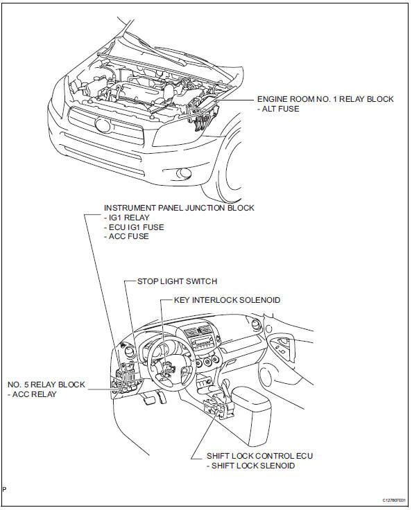
Parts location
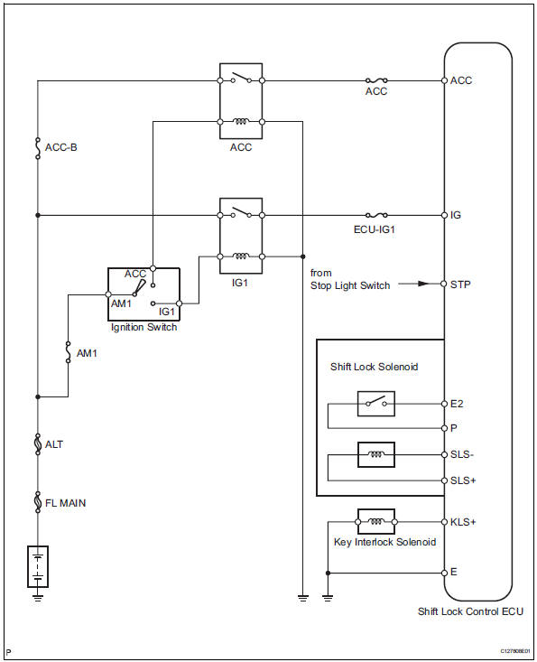
System diagram
On-vehicle inspection
- Check shift lock operation
- Move the shift lever to p.
- Turn the ignition switch off.
- Check that the shift lever cannot be moved to any position other than p.
- Turn the ignition switch on, depress the brake pedal and check that the shift lever can be moved to other positions
- Check shift lock release button operation
- When operating the shift lever with the shift lock release button pressed, check that the lever can be moved to any position other than p. If the operation cannot be performed as specified, check the shift lever assembly.
- Remove key interlock operation
- Turn the ignition switch on.
- Depress the brake pedal and move the shift lever to any position other than p.
- Check that the ignition switch cannot be turned off.
- Move the shift lever to p, turn the ignition switch off and check that the key can be removed. If the results are not as specified, inspect the shift lock control unit.
- Check shift lock control unit assembly
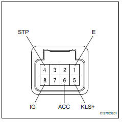
- Measure the voltage of the connector.
Hint:
Do not disconnect the shift lock control ecu connector.
Standard voltage 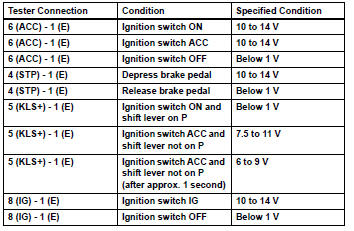
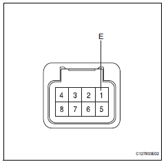
- The resistance of the connector.
Hint:
Do not disconnect the shift lock control ecu connector.
Standard resistance 
If the result is not as specified, replace the shift lock control ecu.
Inspection
- Inspect key interlock solenoid
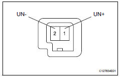
- Disconnect the solenoid connector.
- Connect the battery's positive (+) lead to terminal 1 (un+) and the battery's negative (-) lead to terminal 2 (un-).
Check that the operating noise of the solenoid can be heard.
If the result is not as specified, replace the solenoid.
 Valve body assembly
Components
Removal
Disconnect cable from negative battery
terminal
Caution:
Wait at least 90 seconds after disconnecting the
cable from the negative (-) battery terminal to
preven ...
 Transmission oil cooler
Components
Removal
Remove transmission oil cooler
*1: Disconnect the no. 3 Water by-pass hose from
the transmission oil cooler.
*2: Disconnect the no. 4 Water by-pass hose from
...
Other materials:
Tire pressure warning light circuit
Description
If the tire pressure warning ecu detects trouble, the tire pressure warning
light turns on and tire pressure
monitor is canceled at the same time. At this time, the ecu records a dtc in
memory.
Connect terminals tc and cg of the dlc3 to make the tire pressure warning light
bli ...
Installation (2005/11-2006/01)
Install sliding roof weatherstrip
Install the sliding roof weatherstrip.
Position the joint of the weatherstrip at the rear
center.
Align the marks on the weatherstrip with the
middle marks at the corners of the plastic on
the edge of the sliding roof panel and install the ...
Driver side satellite sensor bus initialization incomplete
Description
The side airbag sensor lh consists of part including the diagnostic circuit
and the lateral deceleration
sensor.
When the center airbag sensor receives signals from the lateral deceleration
sensor, it determines
whether or not the srs should be activated.
Dtc b1643/81 is ...
