Toyota RAV4 (XA40) 2013-2018 Service Manual: Oil pump
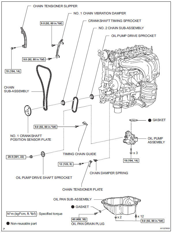
Components
Removal
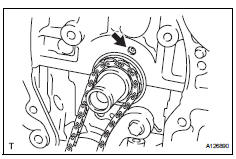
- Remove chain sub-assembly
- Remove the chain (see page em-22).
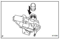
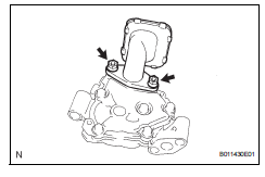
- Remove oil pump assembly
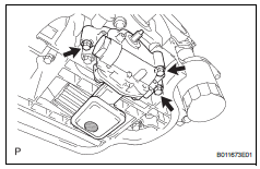
- Remove the 3 bolts, oil pump and gasket.
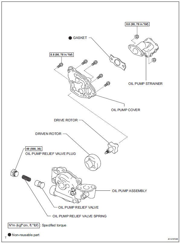
Disassembly
- Remove oil pump strainer
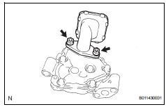
- Remove the 2 nuts, oil pump strainer and gasket.
- Remove oil pump relief valve
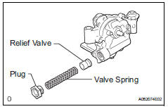
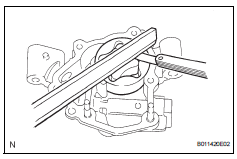
- Using a 27 mm socket wrench, remove the plug.
- Remove the valve spring and relief valve.
- Remove oil pump cover
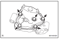
- Remove the 5 bolts and oil pump cover.
Inspection
- Inspect oil jet
- Check the oil jet for damage or clogging.
If necessary, repair the cylinder block.
- Inspect oil pump relief valve
- Check the relief valve.
- Coat the valve with engine oil, and then check
that the valve falls smoothly into the valve hole
by its own weight.
If it does not, replace the relief valve. If necessary, replace the oil pump assembly.
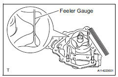
- Inspect oil pump rotor
- Check the side clearance.
- Using a feeler gauge and precision straightedge, measure the clearance between the rotors and precision straightedge.
Standard clearance: 0.030 To 0.085 Mm (0.0012 To 0.0033 In.)
Maximum clearance: 0.16 Mm (0.0063 In.)
If the side clearance is greater than the maximum, replace the oil pump assembly.
- Check the tip clearance.
- Using a feeler gauge, measure the clearance between the drive and driven rotor tips.
Standard clearance: 0.080 To 0.160 Mm (0.0031 To 0.0063 In.)
Maximum clearance: 0.35 Mm (0.0138 In.)
If the tip clearance is greater than the maximum, replace the oil pump assembly.
- Check the body clearance.
- Using a feeler gauge, measure the clearance between the driven rotor and pump body.
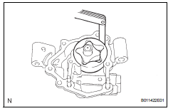
Standard clearance: 0.100 To 0.170 Mm (0.0039 To 0.0067 In.)
Maximum clearance: 0.325 Mm (0.01128 In.)
If the body clearance is greater than the maximum, replace the oil pump assembly.
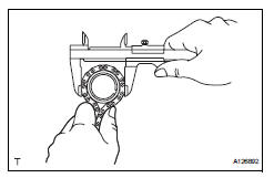
- Inspect oil pump drive chain and 2 oil pump sprockets
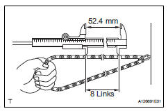
- Using vernier calipers, measure the length of the 8 links with the chain fully stretched.
Maximum chain elongation: 52.4 Mm (2.063 In.)
If the elongation is greater than the maximum, replace the chain.
Hint:
Make the measurements at 3 or more places selected at random.
- Wrap the chain around the oil pump sprocket.
- Using vernier calipers, measure the sprocket diameter with the chain.
Notice:
Vernier calipers must contact the chain rollers when measuring.
Minimum sprocket diameter (with chain): crankshaft 48.2 Mm (1.898 In.) Oil pump drive shaft 48.2 Mm (1.898 In.)
If the diameter is less than the minimum, replace the chain and sprockets.
- Inspect chain tensioner plate
- Measure the chain tensioner plate wear.
Maximum wear: 0.5 Mm (0.020 In.)
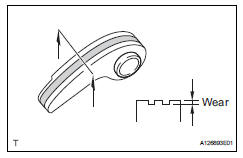
If the wear is greater than the maximum, replace the chain tensioner plate.
Reassembly
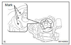
- Install oil pump rotor
- Coat the drive rotor and driven rotor with engine oil.
- Place the drive and driven rotors into the oil pump with the marks facing the pump cover side.
- Install oil pump cover
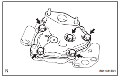
- Install the oil pump cover with the 5 bolts.
Torque: 8.8 N*m (90 kgf*cm, 78 in.*Lbf)
- Install oil pump relief valve
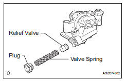
- Coat the relief valve with engine oil.
- Insert the relief valve and spring into the pump body hole.
- Using a 27 mm socket wrench, install the plug.
Torque: 49 n*m (500 kgf*cm, 36 ft.*Lbf)
- Install oil pump strainer
- Install a new gasket and the oil strainer with the 2 nuts.
Torque: 8.8 N*m (90 kgf*cm, 78 in.*Lbf)
Installation
- Install oil pump assembly
- Install a new gasket and the oil pump with the 3 bolts.
Torque: 19 n*m (194 kgf*cm, 14 ft.*Lbf)
- Install chain sub-assembly
- Install the chain (see page em-32).
 Oil filter
Components
Replacement
Caution:
Prolonged and repeated contact with engine oil will
cause the loss of natural oils from the skin, leading to
dryness, irritation and dermatitis. In additi ...
 Brake
Brake
...
Other materials:
Door lock position circuit
Description
This circuit detects the state of the door lock detection sensor and sends it
to the main body ecu.
Wiring diagram
Inspection procedure
Read value of intelligent tester (door lock position)
Connect the intelligent tester (with can vim) to the
dlc3.
Turn the ignitio ...
Rear window wiper and
washer
The rear window wiper and
washer can be used by
operating the lever.
NOTICE
â– When the rear window is dry
Do not use the wiper, as it may
damage the rear window.
Operating the wiper lever
Operating the switch
operates the rear wiper as follows:
*1 or
*2 Off
*1 or
*2 Intermittent
operation
...
Terminals of ecu
Check power steering ecu
Hint:
Measurements cannot be performed on the c connector
side of the power steering ecu.
Measure the voltage and resistance of the
connectors.
If the result is not as specified, the ecu may have a
malfunction. ...
