Toyota RAV4 (XA40) 2013-2018 Service Manual: Short in driver side squib circuit
Description
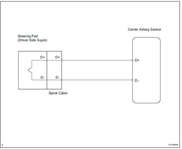
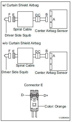
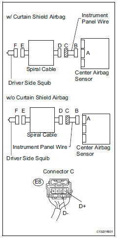
The driver side squib circuit consists of the center airbag sensor, the spiral cable and the steering pad.
The circuit instructs the srs to deploy when the deployment conditions are met.
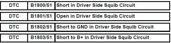
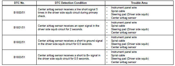
These dtcs are recorded when a malfunction is detected in the driver side squib circuit.
Wiring diagram
Inspection procedure
Hint:
- Perform the simulation method by selecting the "check mode" (signal check) with the intelligent tester (see page rs-52).
- After selecting the "check mode" (signal check), perform the simulation method by wiggling each connector of the airbag system or driving the vehicle on a city or rough road (see page rs-52).
- Check steering pad (driver side squib)
- Turn the ignition switch off.
- Disconnect the cable from the negative (-) battery terminal, and wait for at least 90 seconds.
- Disconnect the connectors from the steering pad.
- Connect the white wire side of sst (resistance 2.1 Ù) to connector e.
Caution:
Never connect a tester to the steering pad (driver side squib) for measurement, as this may lead to a serious injury due to airbag deployment.
Notice:
- Do not forcibly insert sst into the terminals of the connector when connecting.
- Insert sst straight into the terminals of the connector.
Sst 09843-18060
- Connect the cable to the negative (-) battery terminal, and wait for at least 2 seconds.
- Turn the ignition switch on (ig), and wait for at least 60 seconds.
- Clear the dtcs (see page rs-49).
- Turn the ignition switch off.
- Turn the ignition switch on, and wait for at least 60 seconds.
- Check the dtcs (see page rs-49).
Ok: dtc b1800, b1801, b1802, b1803 or 51 is not output.
Hint:
Dtcs other than dtc b1800, b1801, b1802, b1803 or 51 may be output at this time, but they are not related to this check.

- Check connector
- Turn the ignition switch off.
- Disconnect the cable from the negative (-) battery terminal, and wait for at least 90 seconds.
- Disconnect sst from the spiral cable.
- Check that the spiral cable connectors (on the steering pad side) are not damaged.
Ok: lock button is not disengaged, and claw of lock is not deformed or damaged.


- Check driver side squib circuit
- Disconnect the connectors from the center airbag sensor.
- Connect the cable to the negative (-) battery terminal, and wait for at least 2 seconds.
- Turn the ignition switch on.
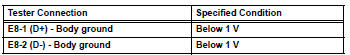
- Measure the voltage of the wire harness side connector
Standard voltage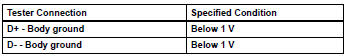
- Turn the ignition switch off.
- Disconnect the cable from the negative (-) battery terminal, and wait for at least 90 seconds.
- Measure the resistance of the wire harness side connector.
Standard resistance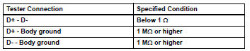
- Release the activation prevention mechanism built into connector b (see page rs-37).
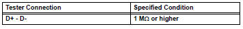
- Measure the resistance of the wire harness side connector.
Standard resistance

- Check instrument panel wire
- Restore the released activation prevention mechanism of connector b to its original position.
- Disconnect the instrument panel wire connector from the spiral cable.
- Connect the cable to the negative (-) battery terminal, and wait for at least 2 seconds.
- Turn the ignition switch on.
- Measure the voltage of the wire harness side connector.
Standard voltage
- Turn the ignition switch off.
- Disconnect the cable from the negative (-) battery terminal, and wait for at least 90 seconds.
- Measure the resistance of the wire harness side connector.
Standard resistance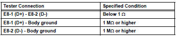
- Release the activation prevention mechanism built into connector b (see page rs-52).
- Measure the resistance of the wire harness side connector.
Standard resistance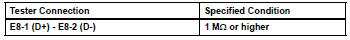

Replace spiral cable
 Passenger airbag on / off indicator circuit malfunction
Description
The passenger airbag on / off indicator circuit consists of the center airbag
sensor and the heater
control panel*1 or *2.
This circuit indicates the operation condition of the ...
 Short in front passenger side squib circuit
Description
The front passenger side squib circuit consists of the center airbag sensor
and the front passenger airbag.
The circuit instructs the srs to deploy when the deployment conditions ...
Other materials:
Emission inspection and maintenance (I/M) programs
Some states have vehicle
emission inspection programs
which include OBD
(On Board Diagnostics)
checks. The OBD system
monitors the operation of
the emission control system.
If the malfunction indicator
lamp comes on
The OBD system determines
that a problem exists somewhere
in the emission control
sy ...
Evaporative emission control system leak detected
Dtc summary
Description
The description can be found in the evap (evaporative emission) system (see
page es-335).
Inspection procedure
Refer to the evap system (see page es-340).
Monitor description
5 Hours* after the ignition switch is turned off, the leak detection pump
creates n ...
Removal and installation of engine intake parts
If any metal particles enter inlet system parts, they
may damage the engine.
When removing and installing inlet system parts,
cover the openings of the removed parts and engine
openings. Use gummed tape or other suitable
materials.
When installing inlet system parts, check that no ...
