Toyota RAV4 (XA40) 2013-2018 Service Manual: Vehicle lift and support locations
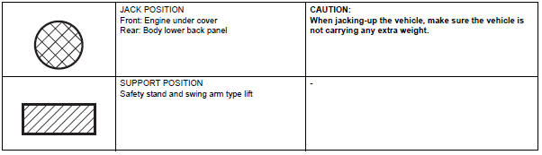
- Notice about vehicle condition when jacking up vehicle
- The vehicle must be unloaded before jacking up / lifting up the vehicle. Never jack up / lift up a heavily loaded vehicle.
- When removing heavy parts such as the engine and transmission, the center of gravity of the vehicle may shift. To stabilize the vehicle, place a balance weight in a location where it will not roll or shift, or use a mission jack to hold the jacking support.
- Notice for using 4 post lift
- Follow the safety procedures outlined in the lift instruction manual.
- Use precautionary measures to prevent the free wheel beam from damaging tires or wheels.
- Use wheel chocks to secure the vehicle.
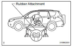
- Notice for using jack and safety stand
- Work on a level surface. Use wheel chocks at all times.
- Use safety stands with rubber attachments as shown in the illustration.
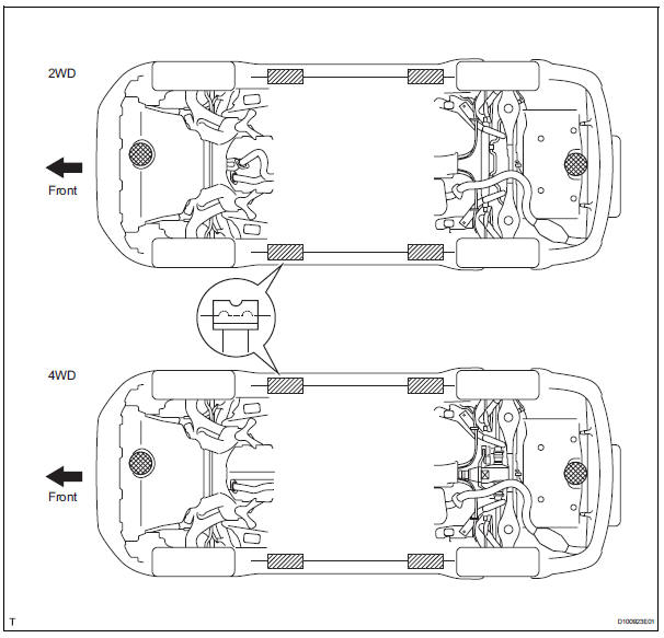
- Set the jack and safety stands to the specified locations of the vehicle accurately.
- When jacking up the vehicle, first release the parking brake and move the shift lever to n.
- When jacking up the entire vehicle:
- When jacking up the front wheels first, make sure wheel chocks are behind the rear wheels.
- When jacking up the rear wheels first, make sure wheel chocks are in front of the front wheels.
- When jacking up only the front or rear wheels of the vehicle:
- Before jacking up the front wheels, place wheel chocks on both sides of the rear wheels.
- Before jacking up the rear wheels, place wheel chocks on both sides of the front wheels.
- When lowering a vehicle that only has its front or rear wheels jacked up:
- Before lowering the front wheels, make sure wheel chocks are in front of the rear wheels.
- Before lowering the rear wheels, make sure wheel chocks are behind the front wheels.
- It is extremely dangerous to perform any work on a vehicle raised on a jack alone, even for work that can be finished quickly. Safety stands must be used to support it.
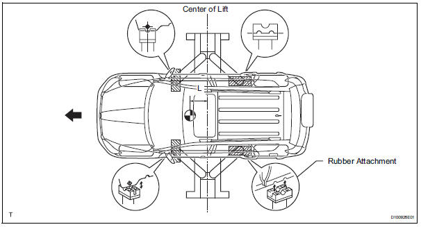
- Notice for using swing arm type lift
- Follow safety procedures outlined in its instruction manual.
- Use a swing arm equipped with a rubber attachment, as shown in the illustration.
- When using the lift, make sure that the vehicle is stabilized so that it will not tilt while work is being performed. Stabilize the vehicle by adjusting the lift arm's length and vehicle's position.
- When using the lift, its center should be as close to the vehicle's center of gravity as possible (length of "l" in the illustration should be as short as possible).
- Set the vehicle on the lift as level as possible. Then match the groove of the cradle to the rigid rack support location.
- Be sure to lock the swing arms before lifting and during work (if equipped with arm locks).
- Lift the vehicle up off the ground. Stand at a safe distance and shake the vehicle to check its stability.
- Notice for using plate type lift
- Follow safety procedures outlined in its instruction manual.
- Use plate lift attachments (rubber lifting blocks) on top of the plate surface.
Refer to the illustration below to determine how to properly set the vehicle.
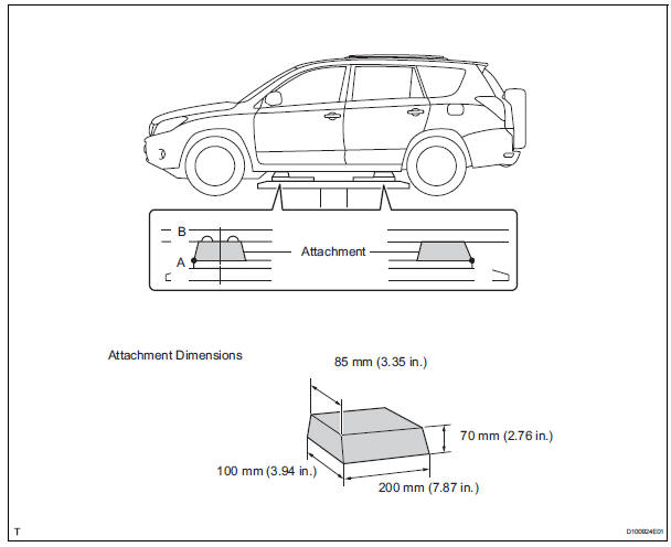
Hint:
| Right and left set position | Place the vehicle over the center of the lift. |
| Front and rear set position | Place the attachments at the ends of the rubber plate surface, under the vehicle lift pad (a and c in the illustration). Raise the plate slightly and reposition the vehicle so the top of the attachment (b in the illustration) is aligned with the front side notch in the vehicle rocker flange. |
- Use the lift to raise the vehicle up off the ground, and shake it to make sure that it is stable.
 Inspection and adjustment of joint angle during removal and
installation of propeller shaft (4wd)
Inspection and adjustment of joint angle during removal and
installation of propeller shaft (4wd)
When performing operations which involve the
removal and installation of the propeller shaft,
always check the joint angle. Make adjustments if
necessary (see page pr-4).
...
 Customize parameters
Notice:
When the customer requests a change in a function,
first make sure that the function can be customized.
Make a note of the current settings before
customizing.
When troubleshooting ...
Other materials:
Child restraint seat tether anchor
Components
Removal
Remove child restraint seat tether anchor cover
Using a screwdriver, detach the 4 claws and remove
the cover.
Hint:
Tape the screwdriver tip before use.
Remove roof headlining assembly
Hint:
It is not necessa ...
Throttle / pedal position sensor / switch "A"
Hint:
These dtcs relate to the throttle position (tp) sensor.
Description
The tp sensor is mounted on the throttle body, and detects the opening angle
of the throttle valve. This
sensor is a non-contact type. It uses hall-effect elements in order to yield
accurate signals even in
extrem ...
Driving in vehicle-to-vehicle distance control mode
This mode employs a radar to detect the presence of vehicles up to
approximately 328 ft. (100 m) ahead, determines the current vehicle-to-
vehicle following distance, and operates to maintain a suitable following
distance from the vehicle ahead. The desired vehicle-to-vehicle
distance can also be se ...
