Toyota RAV4 (XA40) 2013-2018 Service Manual: Brake master cylinder
Components
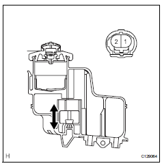
On-vehicle inspection
- Check brake fluid level warning switch
- Remove the reservoir filler cap and strainer.
- Disconnect the brake fluid level warning switch connector.
- Measure the resistance of the switch.
Hint:
There is a float inside the reservoir. Its position can be changed by increasing or decreasing the brake fluid level.
Standard resistance 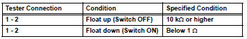
If the value is not as specified, replace the brake master cylinder reservoir sub-assembly.
- Add brake fluid to the max level.
Removal (2005/11-2006/01)
Notice:
- The master cylinder and piston are designed so that the piston can easily fall out. Prevent this by making sure that the tip of the master cylinder points downward when handling the master cylinder.
- Make sure foreign matter does not attach to the master cylinder's piston. If foreign matter attaches, clean it off with a cloth. Then apply lithium soap base glycol grease to the entire outer circumference contact surface area of the piston.
- Remove air cleaner case sub-assembly
- Remove the air cleaner case (see page em-98).
Hint:
Refer to the procedures from the removal of the purge vsv up until the removal of the air cleaner case.
- Drain brake fluid
Notice:
Wash off brake fluid immediately if it comes in contact with any painted surface.
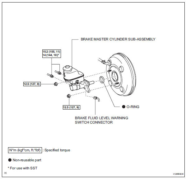
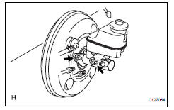
- Remove brake master cylinder subassembly
- Release the vacuum pressure in the brake booster as follows.
- Stop the engine.
- Depress the brake pedal several times.
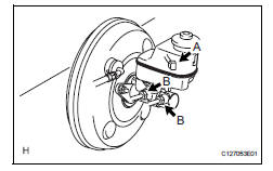
- Disconnect the brake fluid level warning switch connector labeled a.
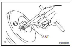
- Using sst, disconnect the 2 brake lines labeled b from the master cylinder.
Sst 09023-00101
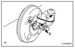
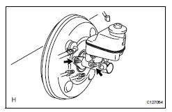
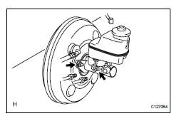
- Remove the 2 nuts.
- Pull out the master cylinder from the brake booster.
Notice:
- The master cylinder and piston are designed so that the piston can easily fall out. Prevent this by making sure that the tip of the master cylinder points downward when handling the master cylinder.
- Make sure foreign matter does not attach to the master cylinder's piston. If foreign matter attaches, clean it off with a cloth. Then apply lithium soap base glycol grease to the entire outer circumference contact surface area of the piston.
- Remove the o-ring from the master cylinder.
Removal (2006/01- )
Notice:
- The master cylinder and piston are designed so that the piston can easily fall out. Prevent this by making sure that the tip of the master cylinder points downward when handling the master cylinder.
- Make sure foreign matter does not attach to the master cylinder's piston. If foreign matter attaches, clean it off with a cloth. Then apply lithium soap base glycol grease to the entire outer circumference contact surface area of the piston.
- Remove air cleaner case sub-assembly (for 2az-fe)
- Remove the air cleaner case (see page em-98).
Hint:
Refer to the procedures from the removal of the purge vsv up until the removal of the air cleaner case.
- Remove air cleaner case (for 2gr-fe)
- Remove the air cleaner case (see page em-21).
Hint:
Refer to the procedures from the removal of the air cleaner cap sub-assembly up until the removal of the air cleaner case.
- Drain brake fluid
Notice:
Wash off brake fluid immediately if it comes in contact with any painted surface.
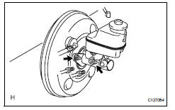
- Remove brake m.der subassembly
- Release the vacuum pressure in the brake booster as follows.
- Stop the engine.
- Depress the brake pedal several times.
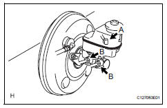
- Disconnect the brake fluid level warning switch connector labeled a.
- Using sst, disconnect the 2 brake lines labeled b from the master cylinder.
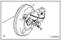
Sst 09023-00101
- Remove the 2 nuts.
- Pull out the master cylinder from the brake booster.
Notice:
- The master cylinder and piston are designed so that the piston can easily fall out. Prevent this by making sure that the tip of the master cylinder points downward when handling the master cylinder.
- Make sure foreign matter does not attach to the master cylinder's piston. If foreign matter attaches, clean it off with a cloth. Then apply lithium soap base glycol grease to the entire outer circumference contact surface area of the piston.
- Remove the o-ring from the master cylinder.
Disassembly
Notice:
- The master cylinder and piston are designed so that the piston can easily fall out. Prevent this by making sure to tip of the master cylinder points downward when handling the master cylinder.
- Make sure foreign matter does not attach to the master cylinder's piston. If foreign matter attaches, clean it off with a cloth. Then apply lithium soap base glycol grease to the entire outer circumference contact surface area of the piston.
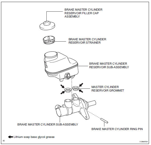
- Remove brake master cylinder ring pin
- Remove brake master cylinder reservoir sub-assembly
- Remove master cylinder reservoir grommet
- Remove brake master cylinder reservoir filler cap assembly
- Remove brake master cylinder reservoir strainer
Inspection
Notice:
- The master cylinder and piston are designed so that the piston can easily fall out. Prevent this by making sure that the tip of the master cylinder points downward when handling the master cylinder.
- Make sure foreign matter does not attach to the master cylinder's piston. If foreign matter attaches, clean it off with a cloth. Then apply lithium soap base glycol grease to the entire outer circumference contact surface area of the piston.
- Inspect and adjust brake booster push rod
Hint:
Adjust the booster push rod when the master cylinder is replaced with a new one. Adjustment is not necessary when the master cylinder is reinstalled and the booster is replaced with a new one.
- Set sst on the master cylinder and lower the rod of
sst until it just touches the piston.
Sst 09737-00013
- Apply chalk to the flat tip of the sst rod. Turn sst
upside down and measure the clearance between
the brake booster push rod and sst.
Standard clearance: -0.21 To 0 mm (-0.0083 To 0 in.)
If there is clearance between the sst main body and the shell of the brake booster, the push rod is protruding too far. If the chalk does not stick to the tip of the brake booster push rod, the push rod protrusion is insufficient.
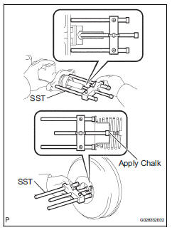
- If the clearance is not within the standard, adjust the length by holding the rod using sst and turning the tip of the rod using a 7 mm socket driver.
Sst 09737-00020
Notice:
Check the push rod clearance again after adjusting.
Reassembly
Notice:
- The master cylinder and piston are designed so that the piston can easily fall out. Prevent this by making sure to tip of the master cylinder points downward when handling the master cylinder.
- Make sure foreign matter does not attach to the master cylinder's piston. If foreign matter attaches, clean it off with a cloth. Then apply lithium soap base glycol grease to the entire outer circumference contact surface area of the piston.
- Install brake master cylinder reservoir strainer
- Install brake master cylinder reservoir filler cap assembly
- Install master cylinder reservoir grommet
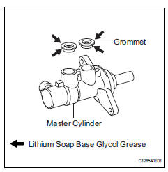
- Apply lithium soap base glycol grease to 2 new grommets, and then install them to the master cylinder.
- Install brake master cylinder reservoir sub-assembly
- Install brake master cylinder ring pin
Installation (2005/11-2006/01)
- Install brake master cylinder subassembly
Notice:
- The master cylinder and piston are designed so that the piston can easily fall out. Prevent this by making sure that the tip of the master cylinder points downward when handling the master cylinder.
- Make sure foreign matter does not attach to the master cylinder's piston. If foreign matter attaches, clean it off with a cloth. Then apply lithium soap base glycol grease to the entire outer circumference contact surface area of the piston.
- Install a new o-ring to the master cylinder.
- Install the master cylinder to the booster with the 2 nuts.
Torque: 12.5 N*m (127 kgf*cm, 9 ft.*Lbf)
- Using sst, connect the 2 brake lines labeled b to the master cylinder.
Sst 09023-00101
Torque: 15.2 N*m (155 kgf*cm, 11 ft.*Lbf) without sst
14 N*m (144 kgf*cm, 10 ft.*Lbf) with sst
Hint:
Use a torque wrench with a fulcrum length of 30 cm (11.81 In.).
- Connect the brake fluid level warning switch connector labeled a to the master cylinder.
- Fill reservoir with brake fluid (see page br- 6)
- Bleed air from brake master cylinder (see page br-7)
- Bleed air from brake line (see page br-7)
- Bleed air from abs and traction actuator assembly (see page br-8)
- Check brake fluid level in reservoir (see page br-6)
- Check for brake fluid leakage
- Install air cleaner case sub-assembly
- Install the air cleaner case (see page em-105).
Hint:
Refer to the procedures from the installation of the air cleaner case up until the installation of the purge vsv.
Installation (2006/01- )
- Install brake master cylinder subassembly
Notice:
- The master cylinder and piston are designed so that the piston can easily fall out. Prevent this by making sure that the tip of the master cylinder points downward when handling the master cylinder.
- Make sure foreign matter does not attach to the master cylinder's piston. If foreign matter attaches, clean it off with a cloth. Then apply lithium soap base glycol grease to the entire outer circumference contact surface area of the piston.
- Install a new o-ring to the master cylinder.
- Install the master cylinder to the booster with the 2 nuts.
Torque: 12.5 N*m (127 kgf*cm, 9 ft.*Lbf)
- Using sst, connect the 2 brake lines labeled b to the master cylinder.
Sst 09023-00101
Torque: 15.2 N*m (155 kgf*cm, 11 ft.*Lbf) without sst
14 N*m (144 kgf*cm, 10 ft.*Lbf) with sst
Hint:
Use a torque wrench with a fulcrum length of 30 cm (11.81 In.).
- Connect the brake fluid level warning switch connector labeled a to the master cylinder.
- Fill reservoir with brake fluid (see page br- 6)
- Bleed air from brake master cylinder (see page br-7)
- Bleed air from brake line (see page br-7)
- Bleed air from abs and traction actuator assembly (see page br-8)
- Check brake fluid level in reservoir (see page br-6)
- Check for brake fluid leakage
- Install air cleaner case sub-assembly (for 2az-fe)
- Install the air cleaner case (see page em-105).
Hint:
Refer to the procedures from the installation of the air cleaner case up until the installation of the purge vsv.
- Install air cleaner case (for 2gr-fe)
- Install the air cleaner case (see page em-31).
Hint:
Refer to the procedures from the installation of the air cleaner case up until the installation of the air cleaner cap sub-assembly.
 Brake pedal
Components
Removal
Disconnect cable from negative battery
terminal
Caution:
Wait at least 90 seconds after disconnecting the
cable from the negative (-) battery terminal to
preven ...
 Brake booster
Installation
(2005/11-2006/01)
Install check valve grommet
Install the grommet to the booster.
Install brake vacuum check valve
assembly
Install the check valve to the grommet ...
Other materials:
Hill-start assist control
When the engine is stopped by
the Stop & Start system when
the vehicle is on an incline,
when the brake pedal is
released, brake force is temporarily
maintained to prevent the
vehicle from rolling backwards
before the engine is restarted
and drive force is generated.
When drive force is generat ...
General maintenance (2005/11-2006/01)
Inspect steering linkage and gear housing
Check the steering wheel free play.
Check the steering linkage for looseness or
damage.
Check that the tie rod ends do not have
excessive play
Check that the dust seals and boots are not
damaged.
Check that the boot clamps are not ...
Idle control system malfunction
Description
The idling speed is controlled by the etcs (electronic throttle control
system). The etcs is comprised
of: 1) the one valve type throttle body; 2) the throttle actuator, which
operates the throttle valve; 3) the
throttle position (tp) sensor, which detects the opening angle of ...
