Toyota RAV4 (XA40) 2013-2018 Service Manual: Brake warning light remains on
Description
If any of the following conditions are detected, the brake warning light remains on:
- The ecu connectors are disconnected from the skid control ecu.
- The brake fluid level is insufficient.
- The parking brake is applied.
- The ebd is defective.
Wiring diagram
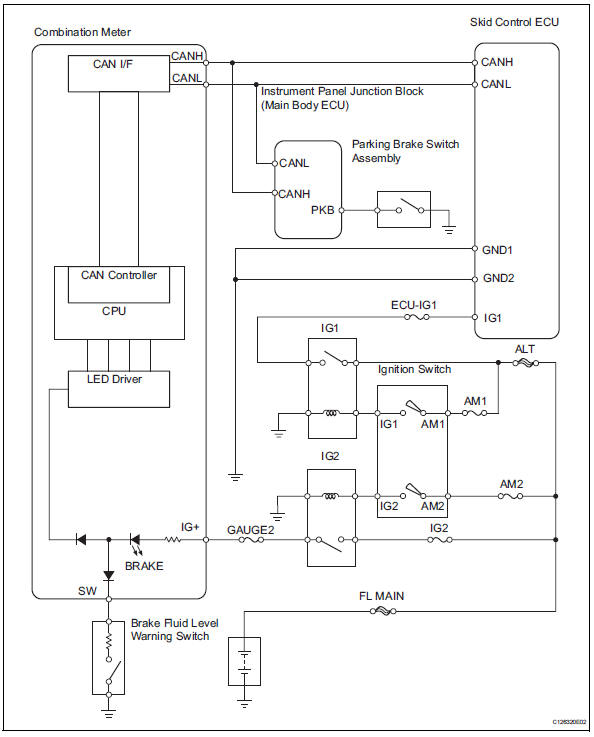
Inspection procedure
- Prepare for inspection
- Check that both of the following conditions are satisfied.
- The brake fluid level in the brake master cylinder reservoir is correct.
- The parking brake is released.
Hint:
When the abs warning light remains illuminated, repair the malfunctions in the abs system first.

- Check dtc for abs
- Check if any abs dtcs are output (see page bc-47).
Result 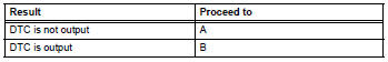

- Check can communication system
- Check if the can communication system dtc is output (see page ca-34).
Result 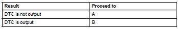

- Inspect skid control ecu connector
- Check if the skid control ecu connector is properly installed.
Ok: the skid control ecu connector is properly installed.

- Check wire harness (skid control ecu - battery and body ground)
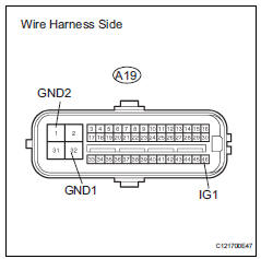
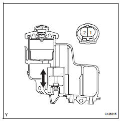
- Disconnect the a19 ecu connector.
- Measure the resistance of the wire harness side connector.
Standard resistance 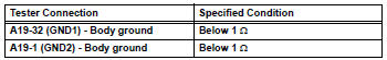
- Measure the voltage of the wire harness side connector.
Standard voltage 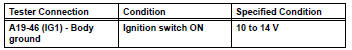

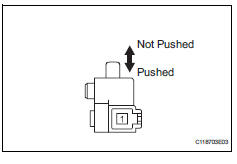
- Read value of intelligent tester (parking brake switch)
- Using the data list, check for proper functioning of the parking brake switch.
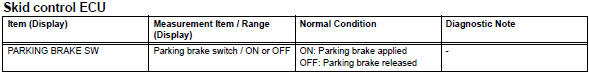
Ok: when the parking brake lever is operated, the display changes as shown above.


- Inspect brake fluid level warning switch
- Remove the reservoir tank cap and strainer.
- Disconnect the brake fluid level warning switch connector.
- Measure the resistance of the switch.
Hint:
A float is placed inside the reservoir. Its position can be changed by increasing or decreasing the brake fluid level.
Standard resistance 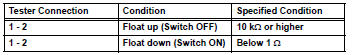
Hint:
If there is no problem after the above check is finished, adjust the brake fluid level to the max level.

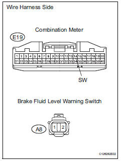
- Check wire harness (level warning switch - combination meter and body ground)
- Disconnect the e19 combination meter connector.
- Disconnect the a8 switch connector.
- Measure the resistance of the wire harness side connectors.
Standard resistance 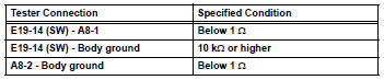

- Inspect combination meter
- Inspect the combination meter (see page me-15).


Replace abs and traction actuator assembly
- Inspect parking brake switch assembly
- Remove the parking brake switch.
- Measure the resistance of the switch.
Standard resistance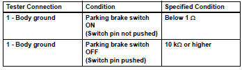

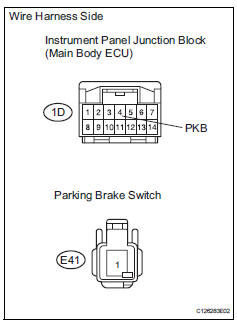
- Check wire harness (junction block - parking brake switch and body ground)
- Disconnect the 1d junction block connector.
- Disconnect the e41 switch connector.
- Measure the resistance of the wire harness side connectors.
Standard resistance 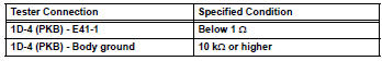

Replace instrument panel junction block
 Vsc warning light does not come on
Description
Refer to the description of "vsc warning light remains on" (see page bc-139).
Wiring diagram
Refer to the vsc warning light circuit (see page bc-140).
Inspection procedure
N ...
 Brake warning light does not come on
Wiring diagram
Refer to the brake warning light circuit (see page bc-145).
Inspection procedure
Check can communication system
Check if the can communication system dtc is output
(see pa ...
Other materials:
Data list / active test
Read data list
Hint:
Using the intelligent tester's data list allows switch,
sensor, actuator and other item values to be read without
removing any parts. Reading the data list early in
troubleshooting is one way to save time.
Connect the intelligent tester to the dlc3.
Turn the igni ...
Fuel Economy
Current fuel economy
Displays the driving range with
remaining fuel.
Average fuel economy
Displays the average fuel economy
since the function was reset or the average fuel economy after starting.* 1,
2, 3
The average fuel economy selected
by "Fuel Economy" on the
screen is displayed.
*1 ...
Precaution
If any of following conditions are met,
keep engine idling with a/c on (engine
speed at less than 2000 rpm) for at least 1
minute:
Refrigerant gas has been refilled or a/c parts have
been replaced.
A long time has elapsed since the engine was
stopped.
Notice:
If the engine s ...
