Toyota RAV4 (XA40) 2013-2018 Service Manual: Vsc warning light does not come on
Description
Refer to the description of "vsc warning light remains on" (see page bc-139).
Wiring diagram
Refer to the vsc warning light circuit (see page bc-140).
Inspection procedure
Notice:
When replacing the abs and traction actuator, perform the zero point calibration (see page bc- 24).
- Inspect can communication system
- Check if the can communication system dtc is output (see page bc-47).
Result 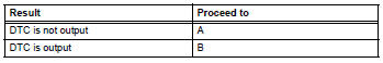


- Perform active test by intelligent tester (vsc warning light)
- Select the active test, generate a control command, and then check that the vsc warning light operates.

Ok: the vsc warning light turns on or off.

- Check combination meter assembly
- Check the combination meter (see page ca-34).

Replace abs and traction actuator assembly
 Vsc warning light remains on
Description
The skid control ecu is connected to the combination meter via the can
communication system.
W/o multi information display:
if the skid control ecu stores any dtcs which relate to t ...
 Brake warning light remains on
Description
If any of the following conditions are detected, the brake warning light
remains on:
The ecu connectors are disconnected from the skid control ecu.
The brake fluid level is insuff ...
Other materials:
Disassembly
Caution:
Wear protective gloves. Sharp areas on the seat frame
(with adjuster) may injure your hands.
Hint:
Use the same procedures for the rh side and lh side.
The procedures listed below are for the lh side.
Remove vertical adjuster cover lh (for driver side)
Using a screw ...
Throttle actuator control motor circuit
Description
The throttle actuator is operated by the ecm and opens and closes the
throttle valve using gears.
The opening angle of the throttle valve is detected by the throttle position (tp)
sensor, which is mounted
on the throttle body. The tp sensor provides feedback to the ecm. This ...
Hood
Release the lock from the inside of the vehicle to open the hood
Pull the hood lock release lever.
The hood will pop up slightly.
Push the auxiliary catch lever to
the left and lift the hood.
Hold the hood open by inserting
the supporting rod into the slot.
Cautio ...
