Toyota RAV4 (XA40) 2013-2018 Service Manual: Check for short circuit
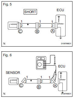
- If the wire harness is ground shorted (fig. 5), Locate the section by conducting a resistance check with the body ground (below).
- Check the resistance with the body ground.
- Disconnect connectors a and c, and measure the resistance
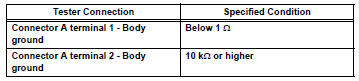
Standard resistance (fig. 6)
 Hint:
Hint:
Measure the resistance while lightly shaking the wire harness vertically and horizontally.
If the results match the examples above, a short circuit exists between terminal 1 of connector a and terminal 1 of connector c.
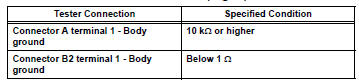
- Disconnect connector b and measure the resistance.
Standard resistance (fig. 7)
 If the results match the examples
above, a short
circuit exists between terminal 1 of connector b2
and terminal 1 of connector c.
If the results match the examples above, a short circuit exists between terminal 1 of connector b2 and terminal 1 of connector c.
 Check for open circuit
For an open circuit in the wire harness in fig. 1,
Check the resistance or voltage, as described below.
Check the resistance.
Disconnect connectors a and c, and measure
the resi ...
 Check and replace ecu
Notice:
The connector should not be disconnected from
the ecu. Perform the inspection from the
backside of the connector on the wire harness
side.
When no measuring condition is specified, ...
Other materials:
Problem symptoms table
Hint:
Use the table below to help determine the cause of the
problem symptom. The potential causes of the symptoms
are listed in order of probability in the "suspected area"
column of the table. Check each symptom by checking the
suspected areas in the order they are listed. Re ...
Installation
Install ignition switch assembly
Install the ignition switch with the 2 screws.
Install the ignition key cylinder light connector.
Install the ignition switch connector.
Install steering column cover lower
Attach the 4 claws to install the steering column
l ...
Freeze frame data
Description
Freeze frame data records the engine conditions (fuel
system, calculated load, engine coolant temperature,
fuel trim, engine speed, vehicle speed, etc.) When a
malfunction is detected. When troubleshooting, it can
help determine if the vehicle was running or stopped, the
engin ...
