Toyota RAV4 (XA40) 2013-2018 Service Manual: Components (2005/11-2006/01)
Sliding roof ecu power source circuit
Description
If the sliding function and tilt function do not operate, there may be a malfunction in the sliding roof ecu power source circuit.
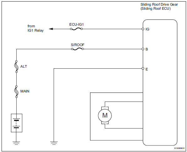
Wiring diagram
Inspection procedure
- Perform active test by intelligent tester (sliding roof operation)
- Select the active test, use the intelligent tester to generate a control command, and then check that the sliding roof operates normally.
Sliding roof ecu
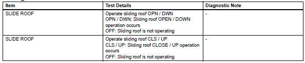
Ok: sliding roof operates normally.

- Inspect fuse (s/roof, ecu-ig1)
- Remove the s/roof and ecu-ig1 fuses from the instrument panel junction block.
- Measure the resistance of the fuses.
Standard resistance:
below 1 

- Check wire harness (sliding roof drive gear - body ground)
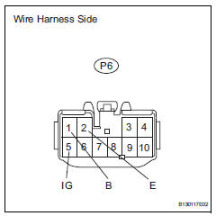
- Disconnect the p6 drive gear connector.
- Measure the voltage and resistance of the wire harness side connector.
Standard voltage 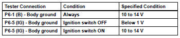
Standard resistance 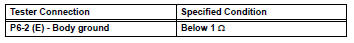

Replace sliding roof drive gear sub-assembly


Other materials:
Vsc warning light remains on
Description
The skid control ecu is connected to the combination meter via the can
communication system.
W/o multi information display:
if the skid control ecu stores any dtcs which relate to the vsc system, the vsc
warning light comes on
in the combination meter.
W/ multi information d ...
Lost communication with front satellite sensor bus lh
Description
The front airbag sensor lh consists of the diagnostic circuit and the frontal
deceleration sensor.
If the center airbag sensor receives signals from the frontal deceleration
sensor, it determines whether or
not the srs should be activated.
Dtc b1607/84, b1608/84, b1617/84 ...
Windshield wipers
and washer
Operating the wiper lever
The wiper operation is selected by moving the lever as follows.
For the u.S.A.
Intermittent operation
Low speed operation
High speed operation
Temporary operation
If equipped, wiper intervals can be adjusted when intermittent operation
is select ...
