Toyota RAV4 (XA40) 2013-2018 Service Manual: Compressor and pulley (for 2az-fe)
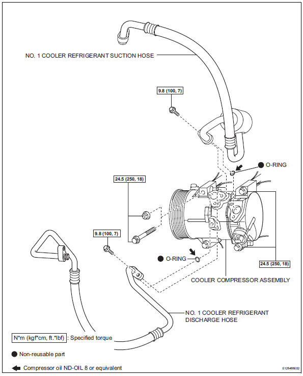
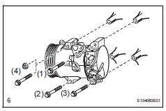
Components
Removal
- Discharge refrigerant from refrigeration system (see page ac-172)
- Disconnect cable from negative battery terminal
Caution:
Wait at least 90 seconds after disconnecting the cable from the negative (-) battery terminal to prevent airbag and seat belt pretensioner activation.
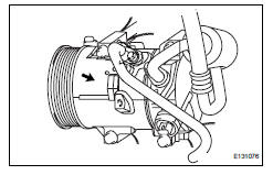
- Disconnect no. 1 Cooler refrigerant suction hose
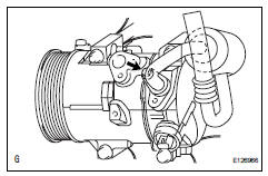
- Remove the bolt and disconnect the cooler refrigerant suction hose from the cooler compressor.
- Remove the o-ring from the cooler refrigerant suction hose.
Notice:
Seal the openings of the disconnected parts using vinyl tape to prevent moisture and foreign matter from entering them.
- Disconnect no. 1 Cooler refrigerant discharge hose
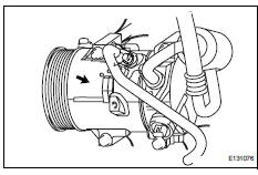
- Remove the bolt and disconnect the cooler refrigerant discharge hose from the cooler compressor.
- Remove the o-ring from the cooler refrigerant discharge hose.
Notice:
Seal the openings of the disconnected parts using vinyl tape to prevent moisture and foreign matter from entering them.
- Remove no. 1 Engine under cover
- Remove fan and generator v belt (see page em-6)
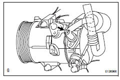
- Remove cooler compressor assembly
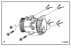
- Disconnect the connector.
- W/o stud bolt: remove the 4 bolts and cooler compressor.
- W/ stud bolt: remove the 3 bolts, nut and cooler compressor.
Installation
- Adjust adjust compressor oil
- When replacing the compressor and magnetic clutch with a new one, gradually discharge the refrigerant gas from the service valve, and drain the following amount of oil from the new compressor and magnetic clutch before installation.
Standard: (oil capacity inside the new compressor and magnetic clutch: 130 + 15 cc (4.6 + 0.51 Fl.Oz.) ) -(Remaining oil amount in the removed compressor and magnetic clutch) = (oil amount to be removed from the new compressor when replacing)
Notice:
- When checking the compressor oil level, observe the precautions on the cooler removal/installation.
- If a new compressor and magnetic clutch is installed without removing some oil remaining in the pipes of the vehicle, the oil amount will be too large. This prevents heat exchange in the refrigerant cycle and causes refrigerant failure.
- If the volume of oil remaining in the removed compressor and magnetic clutch is too small, check for oil leakage.
- Be sure to use nd-oil 8 or equivalent for compressor oil.
- Install cooler compressor assembly
- W/o stud bolt:
install the cooler compressor with the 4 bolts.
Torque: 24.5 N*m (250 kgf*cm, 18 ft.*Lbf)
Notice:
Tighten the bolts in the order shown in the illustration to install the cooler compressor.
- W/ stud bolt:
install the cooler compressor with the 3 bolts and
nut.
Torque: 24.5 N*m (250 kgf*cm, 18 ft.*Lbf)
Notice:
Tighten the bolts in the order shown in the illustration to install the cooler compressor.
- Connect the connector.
- Install no. 1 Cooler refrigerant discharge hose
- Remove the attached vinyl tape from the hose.
- Sufficiently apply compressor oil to a new o-ring and the fitting surface of the cooler compressor.
Compressor oil: nd-oil 8 or equivalent
- Install the o-ring on the cooler refrigerant discharge hose.
- Install the cooler refrigerant discharge hose on the
cooler compressor with the bolt.
Torque: 9.8 N*m (100 kgf*cm, 7 ft.*Lbf)
- Install no. 1 Cooler refrigerant suction hose
- Remove the attached vinyl tape from the hose.
- Sufficiently apply compressor oil to a new o-ring and the fitting surface of the cooler compressor.
Compressor oil: nd-oil 8 or equivalent
- Install the o-ring on the cooler refrigerant suction hose.
- Install the cooler refrigerant suction hose on the cooler compressor with the bolt.
Torque: 9.8 N*m (100 kgf*cm, 7 ft.*Lbf)
- Install fan and generator v belt (see page em-7)
- Install no. 1 Engine under cover
- Connect cable to negative battery terminal
- Charge refrigerant (see page ac-172)
- Warm up engine (see page ac-173)
- Check for leakage of refrigerant (see page ac-173)
 Air mix control servo motor (for automatic air conditioning system)
Components
Removal
Remove air conditioning unit
Remove the air conditioning radiator (see page ac-
185).
Remove air mix control servo motor (see
page ac-191)
Inspection
...
 Compressor and pulley (for 2gr-fe)
Components
Removal
Discharge refrigerant from
refrigeration system (see page ac-172)
Disconnect cable from negative battery
terminal
Caution:
Wait at least 90 seconds after disconne ...
Other materials:
Control module communication bus off
Description
Inspection procedure
The skid control ecu inputs the signals from the ecm, steering angle sensor,
and yaw rate and
acceleration sensor via can communication system.
Check harness and connector (momentary interruption)
Using the data list of the intelligent test ...
Removal (2005/11-2006/01)
Disconnect cable from negative battery
terminal
Caution:
Wait at least 90 seconds after disconnecting the
cable from the negative (-) battery terminal to
prevent airbag and seat belt pretensioner activation.
Remove front door scuff plate lh
Using a screwdriver, detach the 10 cla ...
Propeller shaft system
Problem symptoms table
Hint:
Use the table below to help determine the cause of the
problem symptom. The potential causes of the symptoms are
listed in order of probability in the "suspected area" column of
the table. Check each symptom by checking the suspected
areas in the order th ...
