
Toyota RAV4 (XA40) 2013-2018 Service Manual: Condenser
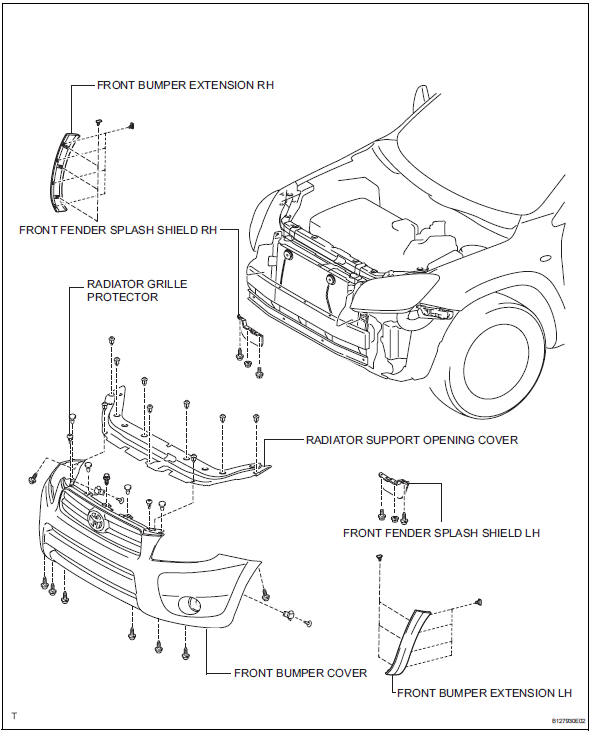
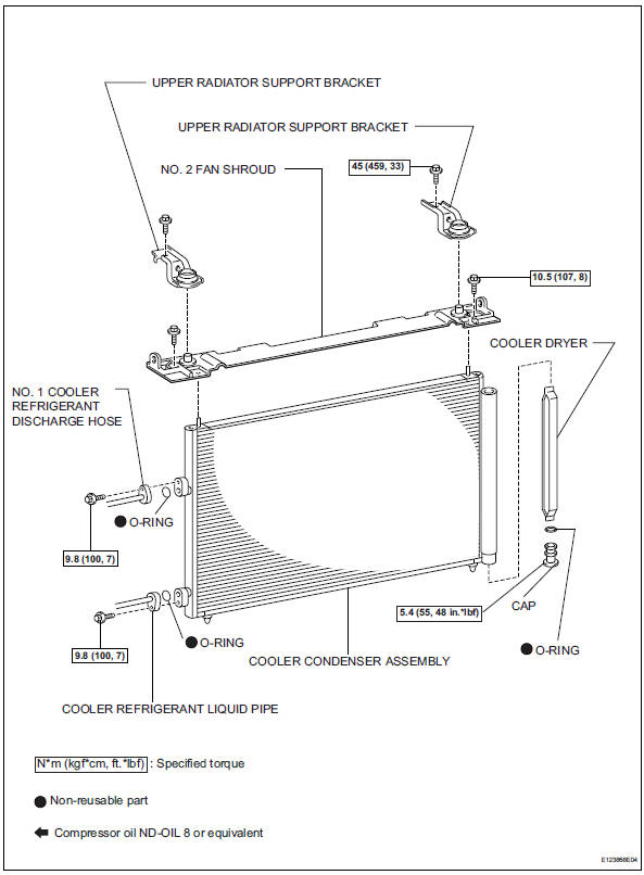
Components
On-vehicle inspection
- Inspect cooler condenser assembly
- If the fins of the cooler condenser are dirty, clean them with water. Dry the fins with compressed air.
Notice:
Do not damage the fins of the condenser.
- If a fin of the cooler condenser is bent, straighten it using a screwdriver or pliers.
- Check condenser for leakage of refrigerant
- Using a halogen leak detector, check the pipe joints for gas leakage.
- If gas leakage is detected in a joint, check the torque of the joint.
Removal
- Discharge refrigerant from refrigeration system (see page ac-172)
- Disconnect cable from negative battery terminal
Caution:
Wait at least 90 seconds after disconnecting the cable from the negative (-) battery terminal to prevent airbag and seat belt pretensioner activation.
- Remove front bumper cover
- Remove front bumper cover (see page et-4).
- Disconnect no. 1 Cooler refrigerant discharge hose
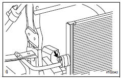
- Remove the bolt and disconnect the cooler refrigerant discharge hose from the cooler condenser.
- Remove the o-ring from the cooler refrigerant discharge hose.
Notice:
Seal the openings of the disconnected parts using vinyl tape to prevent moisture and foreign matter from entering them.
- Disconnect cooler refrigerant liquid pipe
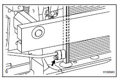
- Remove the bolt and disconnect the cooler refrigerant liquid pipe from the cooler condenser.
- Remove the o-ring from the cooler refrigerant liquid pipe.
Notice:
Seal the openings of the disconnected parts using vinyl tape to prevent moisture and foreign matter from entering them.
- Remove radiator support upper bracket
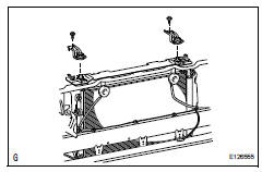
- Remove the 2 bolts and 2 brackets.
- Remove no. 2 Fan shroud
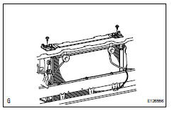
- Remove the 2 bolts and fan shroud.
- Remove cooler condenser assembly
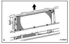
- Remove the cooler condenser.
- Remove cooler dryer
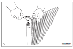
- Using a 14 mm socket hexagon wrench, remove the cap from the modulator.
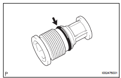
- Remove the o-ring from the cap.
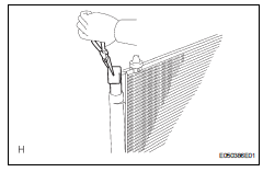
- Using pliers, remove the cooler dryer.
Installation
- Install cooler dryer
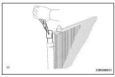
- Using pliers, install the cooler dryer.
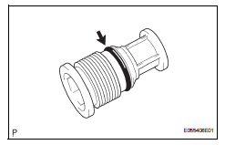
- Apply a sufficient amount of compressor oil to the contact surfaces of a new o-ring and the cap.
Compressor oil: nd-oil 8 or equivalent
- Install the o-ring to the cap.
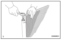
- Using a 14 mm socket hexagon wrench, install the cap to the modulator.
Torque: 2.9 N*m (29 kgf*cm, 25 in.*Lbf)
- Install cooler condenser assembly
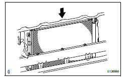
- Install the cooler condenser.
- Install no. 2 Fan shroud
- Install the fan shroud with the 2 bolts.
Torque: 10.5 N*m (107 kgf*cm, 8 ft.*Lbf)
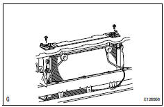
- Install radiator support upper bracket
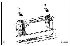
- Install the 2 brackets with the 2 bolts.
Torque: 45 n*m (459 kgf*cm, 33 ft.*Lbf)
- Install cooler refrigerant liquid pipe
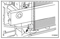
- Remove the attached vinyl tape from the pipe and the connecting part of the cooler condenser.
- Sufficiently apply compressor oil to a new o-ring and the fitting surface of the pipe joint.
Compressor oil: nd-oil 8 or equivalent
- Install the o-ring on the cooler refrigerant liquid pipe.
- Install the cooler refrigerant liquid pipe on the cooler condenser with the bolt.
Torque: 9.8 N*m (100 kgf*cm, 7 ft.*Lbf)
- Install no. 1 Cooler refrigerant discharge hose
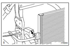
- Remove the attached vinyl tape from the hose and the connecting part of the cooler condenser.
- Sufficiently apply compressor oil to a new o-ring and the fitting surface of the hose joint.
Compressor oil: nd-oil 8 or equivalent
- Install the o-ring on the cooler refrigerant discharge hose.
- Install the cooler refrigerant discharge hose on the cooler condenser with the bolt.
Torque: 9.8 N*m (100 kgf*cm, 7 ft.*Lbf)
- Adjust hood sub-assembly (see page ed-5)
- Install front bumper cover
- Install the front bumper cover (see page et-10).
- Connect cable to negative battery terminal
- Charge refrigerant (see page ac-172)
- Warm up engine (see page ac-173)
- Check for leakage of refrigerant (see page ac-173)
 Compressor and pulley (for 2gr-fe)
Components
Removal
Discharge refrigerant from
refrigeration system (see page ac-172)
Disconnect cable from negative battery
terminal
Caution:
Wait at least 90 seconds after disconne ...
 Room temperature sensor (for automatic ai conditioning system)
Components
Removal
Remove lower instrument panel
Remove the lower instrument panel (see page ip-
16).
Remove room temperature sensor
Disconnect the duct.
Disconnect ...
Other materials:
Can bus line
Description
When any dtc for the can communication system is output, first measure the
resistance between the
terminals of the dlc3 to specify the trouble area, and check that there is not a
short in the can main wire,
between the main wire, to +b, or to gnd.
Wiring diagram
Inspecti ...
Deterioration of battery
Description
The ecm determines the battery power according to the voltage of the batt
terminal while the engine is
running (not cranking).
Inspection procedure
Inspect battery
Inspect the battery specific gravity.
Check the specific gravity of each cell.
Standard gravity: ...
Driving assist systems
To help enhance driving safety and performance, the following
systems operate automatically in response to various driving
situations. Be aware, however, that these systems are supplementary
and should not be relied upon too heavily when operating
the vehicle.
Abs (anti-lock brake system)
Help ...
