Toyota RAV4 (XA40) 2013-2018 Service Manual: Can bus line
Description
When any dtc for the can communication system is output, first measure the resistance between the terminals of the dlc3 to specify the trouble area, and check that there is not a short in the can main wire, between the main wire, to +b, or to gnd.
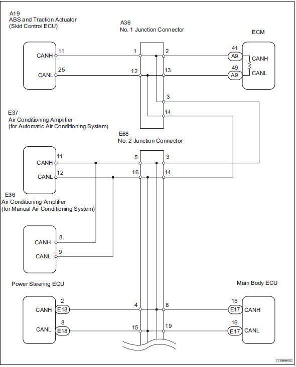
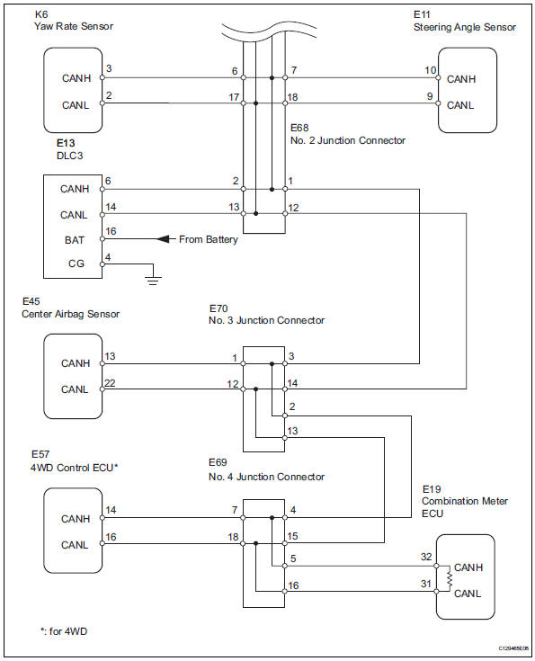
Wiring diagram
Inspection procedure
Notice:
- Turn the ignition switch off before measuring the resistances of the main wire and the branch wire.
- After the ignition switch is turned off, check that the key reminder warning system and light reminder warning system are not in operation.
- Before measuring the resistance, leave the vehicle for at least 1 minute and do not operate the ignition switch, any switches or doors. If doors need to be opened in order to check connectors, open the doors and leave them open.
Hint:
Operating the ignition switch, any switches or any doors triggers related ecu and sensor communication with the can, which causes resistance variation.
- Check can bus wire (main wire for open, can bus lines for short circuit)
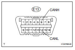
- Measure the resistance of the dlc3.
Standard resistance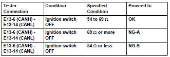

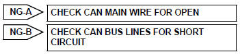
- Check can bus line for short to +b
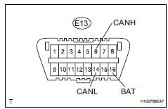
- Measure the resistance of the dlc3.
Standard resistance 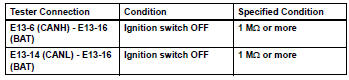

- Check can bus line for short to gnd
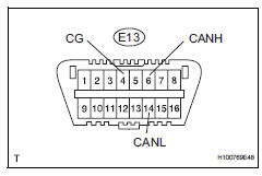
- Measure the resistance of the dlc3.
Standard resistance 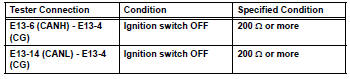

Check how to proceed with troubleshooting
 4Wd control ecu communication stop mode
Description
Hint:
For vehicle with 4wd only.
Wiring diagram
Inspection procedure
Notice:
Turn the ignition switch off before measuring the resistances of the
main wire and the bra ...
 Open in can main wire
Description
There may be an open circuit in the can main wire and / or the dlc3 branch
wire when the resistance
between terminals 6 (canh) and 14 (canl) of the dlc3 is 69 ù or more.
Wi ...
Other materials:
System description
Driver seat belt warning light
When the driver seat belt is not fastened with the
ignition switch on, the driver seat belt warning light
on the combination meter comes on to inform the
driver. The center airbag sensor detects the driver
seat belt status and sends signals to the
co ...
Problem symptoms table (2005/11-2006/01)
Hint:
Use the table below to help determine the cause of the
problem symptom. The potential causes of the symptoms are
listed in order of probability in the "suspected area" column of
the table. Check each symptom by checking the suspected
areas in the order they are listed. Replace p ...
Inner rear view mirror
Components
Removal
Remove inner rear view mirror assembly
Disengage the 2 claws and separate the inner rear
view mirror cover as shown in the illustration.
Remove the inner rear view mirror as shown in the
illustration.
Installation
Install inner rear view mir ...
