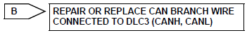
Toyota RAV4 (XA40) 2013-2018 Service Manual: Open in can main wire
Description
There may be an open circuit in the can main wire and / or the dlc3 branch wire when the resistance between terminals 6 (canh) and 14 (canl) of the dlc3 is 69 ù or more.
Wiring diagram
Inspection procedure
Notice:
- Turn the ignition switch off before measuring the resistances of the main wire and the branch wire.
- After the ignition switch is turned off, check that the key reminder warning system and light reminder warning system are not in operation.
- Before measuring the resistance, leave the vehicle for at least 1 minute and do not operate the ignition switch, any switches or doors. If doors need to be opened in order to check connectors, open the doors and leave them open.
Hint:
Operating the ignition switch, any switches or any doors triggers related ecu and sensor communication with the can, which causes resistance variation.
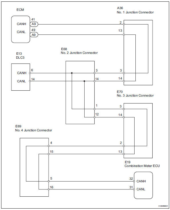
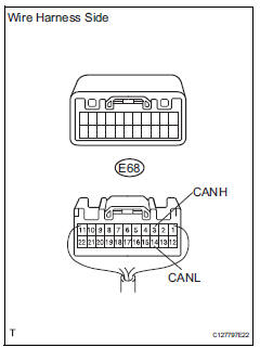
- Check dlc3
- Measure the resistance of the dlc3.
Standard resistance 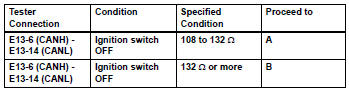
Notice:
When the measured value is 132 ù or more and a can communication system diagnostic trouble code is output, there may be a fault besides disconnection of the dlc3 branch wire. For that reason, troubleshooting should be performed again from "how to proceed with troubleshooting" (see page ca-8) after repairing the trouble area.

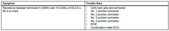
- Check can main wire for disconnection (no. 2 Junction connector - ecm)
- Disconnect the e68 no. 2 Junction connector.
- Measure the resistance of the wire harness side connector.
Standard resistance 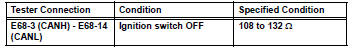

- Check can main wire for disconnection (no. 2 Junction connector - combination meter ecu)
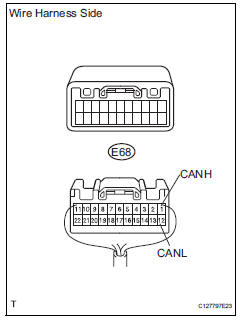
- Measure the resistance of the wire harness side connector.
Standard resistance 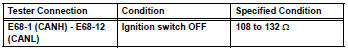

Replace no. 2 Junction connector
- Connect connector
- Reconnect the e68 no. 2 Junction connector.

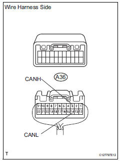
- Check can main wire for disconnection (no. 1 Junction connector - ecm)
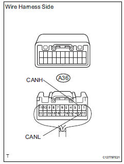
- Disconnect the a36 no. 1 Junction connector.
- Measure the resistance of the wire harness side connector.
Standard resistance 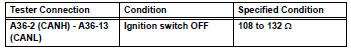

- Check can main wire for disconnection (no. 1 Junction connector - no. 2 Junction connector)
- Measure the resistance of the wire harness side connector.
Standard resistance 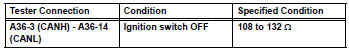

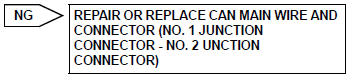
Replace no. 1 Junction connector
- Connect connector
- Reconnect the a36 no. 1 Junction connector.

- Check can main wire for disconnection (ecm - no. 1 Junction connector)
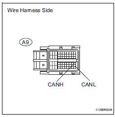
- Disconnect the a9 ecm connector.
- Measure the resistance of the wire harness side connector.
Standard resistance 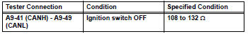

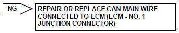
Replace ecm
- Connect connector
- Reconnect the e68 no. 2 Junction connector.

- Check can main wire for disconnection (no. 4 Junction connector - no. 2 Junction connector)
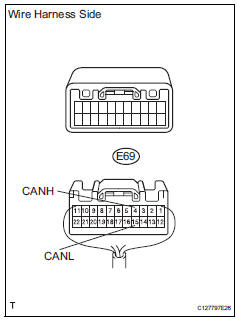
- Disconnect the e69 no. 4 Junction connector.
- Measure the resistance of the wire harness side connector.
Standard resistance 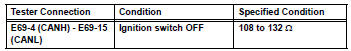


- Check can main wire for disconnection (no. 4 Junction connector - combination meter)
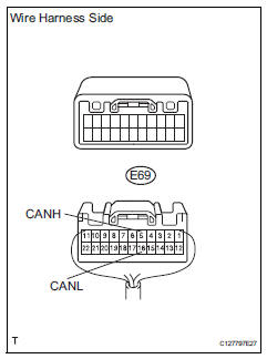
- Measure the resistance of the wire harness side connector.
Standard resistance 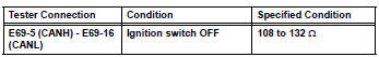


Replace no. 4 Junction connector
- Connect connector
- Reconnect the e69 no. 4 Junction connector.

- Check can main bus line for disconnection (combination meter ecu - no. 4 Junction connector)
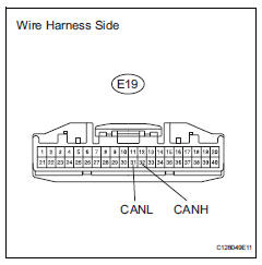
- Disconnect the e19 combination meter ecu connector.
- Measure the resistance of the wire harness side connector.
Standard resistance 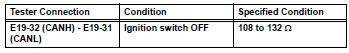

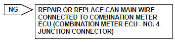
Replace combination meter assembly (combination meter ecu)
- Connect connector
- Reconnect the e69 no. 4 Junction connector.

- Check can main wire for disconnection (no. 2 Junction connector - no. 3 Junction connector)
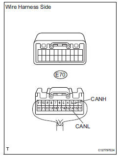
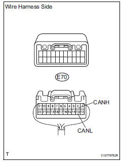
- Disconnect the e70 no. 3 Junction connector.
- Measure the resistance of the wire harness side connector.
Standard resistance 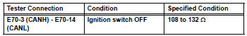

- Check can main wire for disconnection (no. 3 Junction connector - no. 4 Junction connector)
- Measure the resistance of the wire harness side connector.
Standard resistance 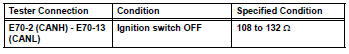

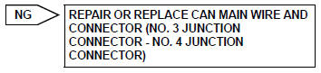
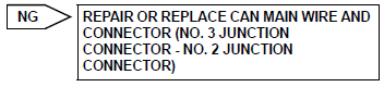
Replace no. 3 Junction connector
 Can bus line
Description
When any dtc for the can communication system is output, first measure the
resistance between the
terminals of the dlc3 to specify the trouble area, and check that there is not a
sho ...
 Short in can bus lines
Description
There may be a short circuit between the can bus lines when the resistance
between terminals 6 (canh)
and 14 (canl) of the dlc3 is below 54
.
Wiring diagram
Inspection ...
Other materials:
Opening/closing the back
door (vehicles with power
back door)
â– Using the wireless remote
control
Press and hold the switch.
The power back door automatically
opens/closes.
Pressing the switch while the power
back door is opening/closing stops
the operation. When the switch is
pressed and held again during the
halted operation, the back door will
perform t ...
Brake
General maintenance
Inspect brake lines and hoses
Hint:
Work in a well-lighted area. Turn the front wheels fully to
the right or left before beginning the inspection.
Using a mirror, check the entire circumference and
length of the brake lines and hoses for:
Damage
Wear
...
How to proceed with troubleshooting
Hint:
*: Use the intelligent tester.
Hint:
If the display indicates a communication fault in the tester,
inspect the dlc3.
Hint:
Record or print dtcs and freeze frame data, if necessary.
Hint:
If the engine does not start, first perform the "check dtc"
procedures a ...
