Toyota RAV4 (XA40) 2013-2018 Service Manual: Ecu power source circuit
Description
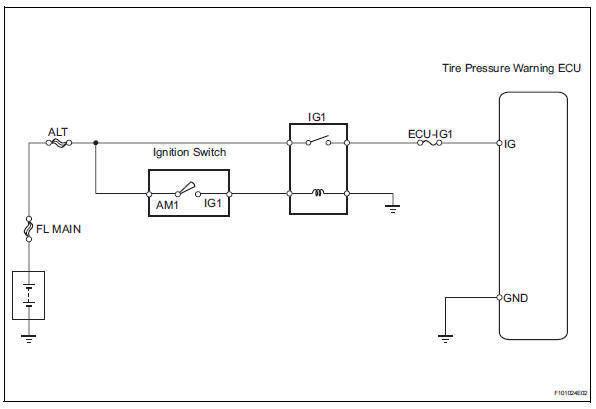
This is the power source for the tire pressure warning ecu.
Wiring diagram
Inspection procedure
Notice:
It is necessary to register an id code after replacing the tire pressure monitor valve and/or the tire pressure warning ecu (see page tw-9).
- Inspect fuse (ecu-ig1)
- Remove the ecu-ig1 fuse from the instrument panel junction block.
- Measure the resistance of the fuse.
Standard resistance:
below 1 

- Inspect ig1 relay
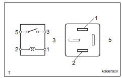
- Remove the ig1 relay from the instrument panel junction block.
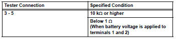
- Measure the resistance of the relay.
Standard resistance


- Inspect wire harness (ecu - battery and body ground)
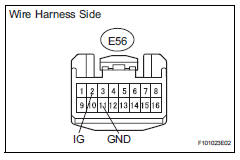
- Disconnect the e56 ecu connector.
- Measure the voltage of the wire harness side connector.
Standard voltage 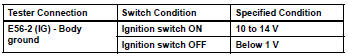
- Measure the resistance of the wire harness side connector.
Standard resistance 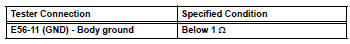

Proceed to next circuit inspection shown in problem symptoms table
 Tire pressure warning light circuit
Description
If the tire pressure warning ecu detects trouble, the tire pressure warning
light turns on and tire pressure
monitor is canceled at the same time. At this time, the ecu records a dtc i ...
 Tire pressure warning receiver (w/ antenna)
Components
...
Other materials:
Transmitter id
Description
Hint:
It is necessary to perform the procedure to identify the tire pressure
monitor valve that is malfunctioning
because it cannot be identified by the output dtc.
Inspection procedure
Notice:
It is necessary to register an id code after replacing the tire pressure
wa ...
Receiver error
Description
Wiring diagram
Inspection procedure
Notice:
It is necessary to register an id code after replacing the tire pressure
warning valve abd
transmitter and/or the tire pressure warning ecu (see page tw-9).
Hint:
Set the tire pressure to the specified value.
Standard pres ...
Windshield wipers and
washer
Operating the lever can
switch between automatic
operation and manual operation,
or can use the
washer.
NOTICE
â– When the windshield is dry
Do not use the wipers, as they
may damage the windshield.
Operating the wiper lever
Operating the lever operates
the wipers or washer as follows:
Intermittent ...
