Toyota RAV4 (XA40) 2013-2018 Service Manual: Throttle / pedal position sensor / switch "d" circuit range / performance
Description
Hint:
Refer to dtc p2120 (see page es-282).

Monitor description
When the difference between the output voltages of vpa and vpa2 deviates from the standard, the ecm determines that the accelerator pedal position (app) sensor is malfunctioning. The ecm turns on the mil and the dtc is set.
Monitor strategy
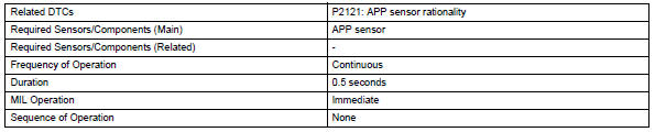
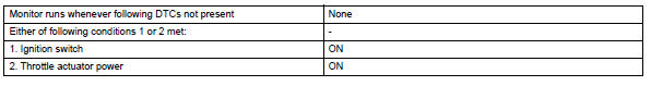
Typical enabling conditions
Typical malfunction thresholds
![]()
Fail-safe
The app sensor has two (main and sub) sensor circuits. If a malfunction occurs in either of the sensor circuits, the ecm detects the abnormal signal voltage difference between the two sensor circuits and switches to limp mode. In limp mode, the functioning circuit is used to calculate the accelerator pedal opening angle to allow the vehicle to continue driving. If both circuits malfunction, the ecm regards the opening angle of the accelerator pedal as being fully closed. In this case, the throttle valve remains closed as if the engine is idling.
If a pass condition is detected and then the ignition switch is turned off, the fail-safe operation stops and the system returns to a normal condition.
Wiring diagram
Refer to dtc p2120 (see page es-286).
Inspection procedure
Hint:
Read freeze frame data using the intelligent tester. Freeze frame data records the engine condition when malfunctions are detected. When troubleshooting, freeze frame data can help determine if the vehicle was moving or stationary, if the engine was warmed up or not, if the air-fuel ratio was lean or rich, and other data from the time the malfunction occurred.
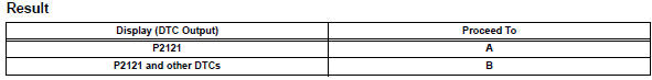
- Check any other dtcs output (in addition to dtc p2121)
- Connect the intelligent tester to the dlc3.
- Turn the ignition switch on.
- Turn the tester on.
- Select the following menu items: diagnosis / enhanced obd ii / dtc info / current codes.
- Read dtcs.
Hint:
If any dtcs other than p2121 are output, troubleshoot those dtcs first.


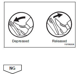
- Read value using intelligent tester (accel pos #1 and accel pos #2)
- Connect the intelligent tester to the dlc3.
- Turn the ignition switch on and turn the tester on.
- Select the following menu items: diagnosis / enhanced obd ii / data list / primary / accel pos #1 and accel pos #2.
- Read the values displayed on the tester.
Standard voltage 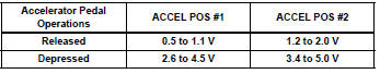
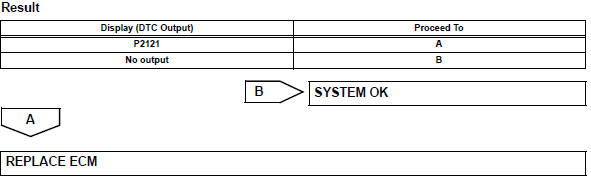
- Replace accelerator pedal assembly

- Check whether dtc output recurs (dtc p2121)
- Connect the intelligent tester to the dlc3.
- Turn the ignition switch o on and turn the tester on.
- Clear dtcs (see page es-35).
- Start the engine.
- Allow the engine to idle for 15 seconds.
- Select the following menu items: diagnosis / enhanced obd ii / dtc info / current codes.
- Read dtcs.
 Throttle / pedal position sensor
Hint:
These dtcs relate to the accelerator pedal position (app) sensor.
Description
Hint:
This etcs (electronic throttle control system) does not use a throttle cable.
The app sensor is mou ...
 Oxygen (a/f) sensor signal stuck
Hint:
Although the dtc titles say oxygen sensor, these dtcs relate to the
air-fuel ratio (a/f) sensor.
Sensor 1 refers to the sensor mounted in front of the three-way
catalytic convert ...
Other materials:
Srs warning light remains on
Description
The srs warning light is located on the combination meter.
When the srs is normal, the srs warning light comes on for approximately 6
seconds after the ignition
switch is turned from off to on, and then goes off automatically.
If there is a malfunction in the srs, the srs warni ...
Back door
The back door can be
locked/unlocked and
opened/closed by the following
procedures.
WARNING
Observe the following precautions.
Failure to do so may result in
death or serious injury.
â– Before driving
Make sure that the back door is
fully closed.
If the back door is not fully
closed, it may op ...
Tc and cg terminal circuit
Description
Connecting terminals tc and cg of the dlc3 causes the skid control ecu to
display 2-digit dtcs by
flashing the abs warning light.
Wiring diagram
Inspection procedure
Check dlc3 (tc voltage)
Turn the ignition switch on.
Measure the voltage of the dlc3.
Standar ...
