
Toyota RAV4 (XA40) 2013-2018 Service Manual: How to proceed with troubleshooting (2006/01- )
Hint:
- Use these procedures to troubleshoot the air conditioning system.
- *: Use the intelligent tester.
- Vehicle brought to workshop

- Customer problem analysis and symptom check

- Inspect battery voltage
Standard voltage: 11 to 14 v
If the voltage is below 11 v, recharge or replace the battery before proceeding.

- Check can communication system*
- Use the intelligent tester to check if the can communication system is functioning.
Result 


- Check dtc or check sensor check code through panel diagnosis*
- Check dtcs or sensor check codes.
- Write down the dtcs or sensor check codes.
- Clear the dtcs or sensor check codes.
- Check whether the dtcs or sensor check codes recur.
- Reproduce the problem symptoms in accordance with the dtcs or sensor check codes that were written down, and check whether the dtcs or sensor check codes recur.
Hint:
Refer to the dtc chart when any dtcs or sensor check codes are output.
Result 


- Refer to problem symptoms table
Result 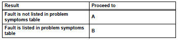


- Overall analysis and troubleshooting*
- Data list / active test (see page ac-37)
- Panel diagnosis (indicator check) (see page ac-31)
- Panel diagnosis (sensor check) (see page ac-31)
- Panel diagnosis (actuator check) (see page ac-31)
- Terminals of ecu (see page ac-27)

- Adjust, repair or replace

- Confirmation test

End
 How to proceed with troubleshooting (2005/11-2006/01)
Hint:
Use these procedures to troubleshoot the air conditioning
system.
*: Use the intelligent tester.
Vehicle brought to workshop
Customer problem analysis and symptom check
...
 Customize parameters
Hint:
The following items can be customized.
Notice:
When the customer requests a change in a function,
first make sure that the function can be customized.
Be sure to make a note of the cur ...
Other materials:
Front speed sensor
Components
Removal
Hint:
Use the same procedures for the lh side and rh side.
The procedures listed below are for the lh side.
Disconnect cable from negative battery
terminal
Caution:
Wait at least 90 seconds after disconnecting the
cable from the negative (-) battery termin ...
Front wiper motor and link
Components
Removal
Disconnect cable from negative battery
terminal
Caution:
Wait at least 90 seconds after disconnecting the
cable from the negative (-) battery terminal to
prevent airbag and seat belt pretensioner activation.
Remove front wiper arm head cap
Remove the 2 c ...
Summary of the blind spot monitor
The blind spot monitor is a system that has 2 functions;
The blind spot monitor function
Assists the driver in making the decision when changing lanes
The rear cross traffic alert function
Assists the driver when backing up
These functions use same sensors.
Bsm main switch
...
