Toyota RAV4 (XA40) 2013-2018 Service Manual: Tire pressure warning light circuit
Description
If the tire pressure warning ecu detects trouble, the tire pressure warning light turns on and tire pressure monitor is canceled at the same time. At this time, the ecu records a dtc in memory.
Connect terminals tc and cg of the dlc3 to make the tire pressure warning light blink and output the dtc.
Wiring diagram
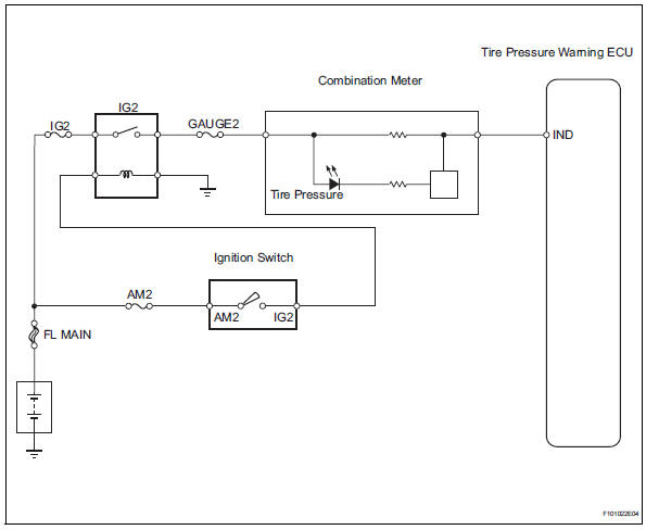
Inspection procedure
Notice:
It is necessary to register an id code after replacing the tire pressure monitor valve and/or the tire pressure warning ecu (see page tw-9).
- Inspect fuse (gauge)
- Remove the gauge fuse from the instrument panel junction block.
- Measure the resistance of the fuse.
Standard resistance:
below 1 


- Check tire pressure warning light circuit
- Disconnect the e56 ecu connector.
- Using a service wire, connect e56-6 (ind) on the wire harness side and body ground.
- Turn the ignition switch on.
- Check that the tire pressure warning light turns on.
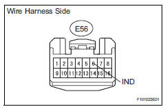
Ok: tire pressure warning light turns on.

- Check wire harness (ecu - meter)
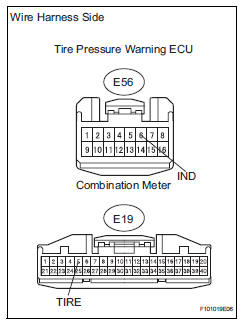
- Disconnect the e56 ecu connector.
- Disconnect the e19 meter connector.
- Measure the resistance of the wire harness side connectors.
Standard resistance 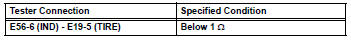

Proceed to next circuit inspection shown in problem symptoms table
 Vehicle speed signal error (test mode dtc)
Description
The tire pressure warning ecu receives a speed signal from the combination
meter. This dtc is stored
upon entering test mode, and cleared when a vehicle speed signal of 12 mph (20 ...
 Ecu power source circuit
Description
This is the power source for the tire pressure warning ecu.
Wiring diagram
Inspection procedure
Notice:
It is necessary to register an id code after replacing the tire pressure
...
Other materials:
Evaporative emission leak detection pump
Dtc summary
Hint:
The leak detection pump is built into the canister pump module.
Description
The description can be found in the evap (evaporative emission) system (see
page es-335).
Inspection procedure
Refer to the evap system (see page es-340).
Monitor description
5 Hours* afte ...
Problem symptoms table (2006/01- )
Hint:
Use the table below to help determine the cause of the
problem symptom. The potential causes of the symptoms
are listed in order of probability in the "suspected area"
column of the table. Check each symptom by checking the
suspected areas in the order they are listed. Re ...
Problem symptoms table
Hint:
Use the table below to help determine the cause of the
problem symptom. The potential causes of the symptoms
are listed in order of probability in the "suspected area"
column of the table. Check each symptom by checking the
suspected areas in the order they are listed. Re ...
