
Toyota RAV4 (XA40) 2013-2018 Service Manual: Problem symptoms table (2005/11-2006/01)
Hint:
Use the table below to help determine the cause of the problem symptom. The potential causes of the symptoms are listed in order of probability in the "suspected area" column of the table. Check each symptom by checking the suspected areas in the order they are listed. Replace parts as necessary.
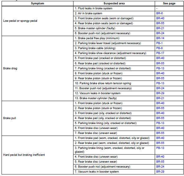
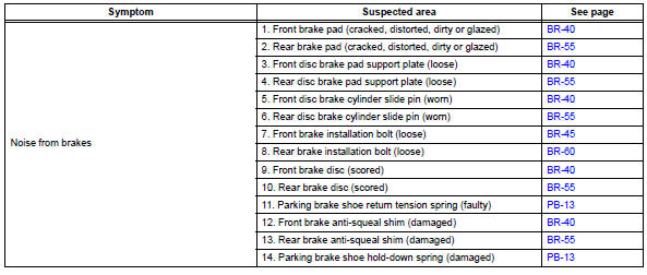
 Precaution
Notice:
Take extra care to replace each part properly. Improper
installation or repair could affect the performance of
the brake system and cause a driving hazard.
It is very important to ke ...
 Problem symptoms table (2006/01- )
Hint:
Use the table below to help determine the cause of the
problem symptom. The potential causes of the symptoms are
listed in order of probability in the "suspected area" column
of th ...
Other materials:
Back door
The back door can be
locked/unlocked and
opened/closed by the following
procedures.
WARNING
Observe the following precautions.
Failure to do so may result in
death or serious injury.
â– Before driving
Make sure that the back door is
fully closed.
If the back door is not fully
closed, it may op ...
Valve body
Components
Disassembly
Remove shift solenoid valve slt
Remove the bolt, plate and shift solenoid valve slt
from the valve body.
Remove shift solenoid valve sl1
Remove the bolt, plate and shift solenoid valve sl1
from the valve body.
Remove shift solenoid ...
How to proceed with troubleshooting
Hint:
Use these procedures to troubleshoot the supplemental
restraint system.
*: Use the intelligent tester.
Vehicle brought to workshop
Inspect battery voltage*
Standard voltage:
11 to 14 v
If the voltage is below 11 v, recharge or replace the battery
before proceeding.
...
